|
|
|
PDF TL-T5ME2 Data sheet ( Hoja de datos )
| Número de pieza | TL-T5ME2 | |
| Descripción | Slim Proximity Sensor | |
| Fabricantes | Omron | |
| Logotipo | ||
Hay una vista previa y un enlace de descarga de TL-T5ME2 (archivo pdf) en la parte inferior de esta página. Total 14 Páginas | ||
|
No Preview Available !
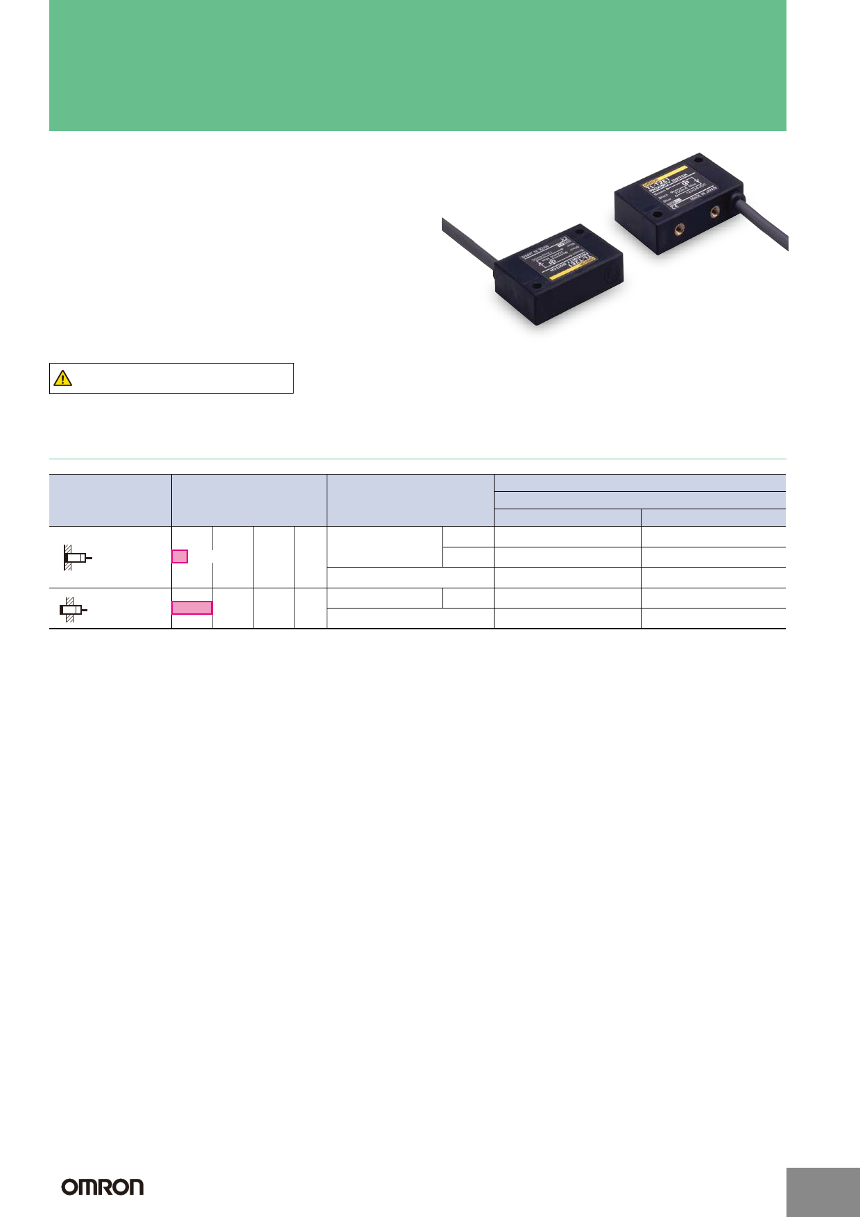
Slim Proximity Sensor
TL-T
Slim Model of Width 12 mm.
• Ideal for side-by-side mounting.
Be sure to read Safety Precautions on page 5.
Ordering Information
Appearance
Sensing distance
Output specifications
Model
Output configuration
Shielded
2 mm
DC 3-wire models
AC 2-wire models
NPN
PNP
NO
TL-T2E1
TL-T2F1
TL-T2Y1
NC
TL-T2E2
---
TL-T2Y2
Unshielded
5 mm
DC 3-wire models NPN
AC 2-wire models
TL-T5ME1
TL-T5MY1
TL-T5ME2
TL-T5MY2
Note: Models with a different frequency are available. The model numbers are TL-T@@@5. (e.g., TL-T2E15).
http://www.ia.omron.com/
(c)Copyright OMRON Corporation 2008 All Rights Reserved.
1
1 page 
Safety Precautions
WARNING
This product is not designed or rated for
ensuring safety of persons.
Do not use it for such purposes.
• Do not short the load. Explosion or burning may
result.
• Do not supply power to the Sensor with no load
connected, otherwise internal parts may be
damaged or burnt.
Applicable Models: AC 2-wire Models
Precautions for Correct Use
Do not use this product under ambient conditions that exceed
the ratings.
● Design
Effect of Surrounding Metals
• Be sure to separate the Sensor from surrounding metal
objects as shown in the following illustration.
12 mm
15 mm
25 mm
15 mm 15 mm
15 mm
15 mm
TL-T
Mutual Interference
When two or more Sensors are mounted face-to-face or side-
by-side, separate them as shown below. The table below
indicates the minimum distances A and B.
AB
Mutual Interference
(Unit: mm)
Model
TL-T2
TL-T5
Distance
A
40 (10)
120 (60)
B
12 (0)
80 (40)
Note: Figures in parentheses will apply if the Sensors in use are different from
each other in response frequency.
● Mounting
• At the time of rear mounting, be sure that the tightening
torque does not exceed 0.59 N·m.
Mounting screw
0.59 N·m
• At the time of side mounting, be sure that the tightening
torque does not exceed 0.78 N·m.
• The TL-T2 will not be influenced by metal when it is
embedded in metal.
Mounting screw
0.78 N·m
Dimensions
TL-T@
(Unit: mm)
Unless otherwise specified, the tolerance class IT16 is used for dimensions in this data sheet.
Indicator *2
Two, 3.1-dia. holes
4 *1
32±0.2
6
Sensing surface
4 17±0.2
26
Two, M3, depth 6
12
5
9
16±0.2 40
*1. DC-switching model: 4.0-dia.
vinyl-insulated round cable
with 3 conductors (Conductor
cross section: 0.2 mm2,
Insulator diameter: 1.2 mm),
Standard length: 2 m
AC-switching model: 4.0-dia.
vinyl-insulated round cable
with 2 conductors (Conductor
cross section: 0.3 mm2,
Insulator diameter: 1.3 mm),
Standard length: 2 m
*2. Detection indicator (red)
In the interest of product improvement, specifications are subject to change without notice.
http://www.ia.omron.com/
(c)Copyright OMRON Corporation 2008 All Rights Reserved.
5
5 Page 
Proximity Sensors Technical Guide
●Wiring Considerations
AND/OR Connections for Proximity Sensors
Model
Type of
connection
Connection
AND (series
connection)
DC 2-Wire
OR (parallel
connection)
+
-
+
-
+
-
+
Load
Load
Load
Description
Keep the number of connected Sensors (N) within the range of the following
equation.
VS - N × VR ≥ Operating load voltage
N : Number of Sensors that can be connected
Vs
VR: Residual output voltage of Proximity Sensor
VS: Power voltage
It is possible, however, that the indicators may not light correctly and error
pulses (of approximately 1 ms) may be generated because the rated power
supply voltage and current are not supplied to individual Proximity Sensors.
Verify that this is not a problem before operation.
Keep the number of connected Sensors (N) within the range of the following
equation.
Vs N × i ≤ Load reset current
N: Number of Sensors that can be connected
i: Leakage current of Proximity Sensor
Example: When an MY (24-VDC) Relay is used as the load, the maximum
number of Sensors that can be connected is 4.
<TL-NY, TL-MY, E2K-@MY@, TL-T@Y>
The above Proximity Sensors cannot be used in a series connection. If need-
ed, connect through relays.
VS
AND (series
connection)
<E2E-X@Y>
X1 X2 Load
For the above Proximity Sensors, the voltage VL that can be applied to the
X1 VS
load when ON is VL = VS - (Output residual voltage × Number of Sensors), for
both 100 VAC and 200 VAC.
X2 The load will not operate unless VL is higher than the load operating voltage.
This must be verified before use.
Load
When using two or more Sensors in series with an AND circuit, the limit is three
Sensors. (Be careful of the VS value in the diagram at left.)
VL
VS
VS ≥ 100V
AC 2-wire
In general it is not possible to use two or more Proximity Sensors in parallel
with an OR circuit.
(A) (B)
Load
A parallel connection can be used if A and B will not be operated simulta-
neously and there is no need to hold the load. The leakage current, however,
will be n times the value for each Sensor and reset failures will frequently oc-
cur.
("n" is the number of Proximity Sensors.)
OR (parallel
connection)
(A)
X1
X2 Load
(B)
X1 X2
If A and B will be operated simultaneously and the load is held, a parallel con-
nection is not possible.
If A and B operate simultaneously and the load is held, the voltages of both A
and B will fall to about 10 V when A turns ON, and the load current will flow
through A causing random operation. When the sensing object approaches B,
the voltage of both terminals of B is too low at 10 V and the switching element
of B will not operate. When A turns OFF again, the voltages of both A and B
rise to the power supply voltage and B is finally able to turn ON.
During this period, there are times when A and B both turn OFF (approximately
10 ms) and the loads are momentarily restored. In cases where the load is to
be held in this way, use a relay as shown in the diagram at left.
Note: When AND/OR connections are used with Proximity Sensors, the effects of erroneous pulses or leakage current may prevent use. Verify that there are no
problems before use.
http://www.ia.omron.com/
(c)Copyright OMRON Corporation 2008 All Rights Reserved.
C-6
11 Page | ||
| Páginas | Total 14 Páginas | |
| PDF Descargar | [ Datasheet TL-T5ME2.PDF ] | |
Hoja de datos destacado
| Número de pieza | Descripción | Fabricantes |
| TL-T5ME1 | Slim Proximity Sensor | Omron |
| TL-T5ME2 | Slim Proximity Sensor | Omron |
| Número de pieza | Descripción | Fabricantes |
| SLA6805M | High Voltage 3 phase Motor Driver IC. |
Sanken |
| SDC1742 | 12- and 14-Bit Hybrid Synchro / Resolver-to-Digital Converters. |
Analog Devices |
|
DataSheet.es es una pagina web que funciona como un repositorio de manuales o hoja de datos de muchos de los productos más populares, |
| DataSheet.es | 2020 | Privacy Policy | Contacto | Buscar |