|
|
|
PDF A7506 Data sheet ( Hoja de datos )
| Número de pieza | A7506 | |
| Descripción | 1.2MHz CONSTANT FREQUENCY SYNCHRONUS STEP-UP DC-DC CONVERTER | |
| Fabricantes | AiT Semiconductor | |
| Logotipo | ||
Hay una vista previa y un enlace de descarga de A7506 (archivo pdf) en la parte inferior de esta página. Total 13 Páginas | ||
|
No Preview Available !
AiT Semiconductor Inc.
www.ait-ic.com
A7506
600mA, 1.2MHz CONSTANT FREQUENCY
SYNCHRONUS STEP-UP DC-DC CONVERTER
DESCRIPTION
FEATURES
The A7506 is synchronous, fixed frequency, step-up
High Efficiency: Up to 92%
DC/DC converters delivering high efficiency in a
1.2MHz Constant Switching Frequency
6-lead SOT package. Capable of supplying 3.3V at
3.3V Output Voltage at IOUT=100mA from a Single
100mA from a single AA cell input, the device
AA Cell; 5.0V Output Voltage at IOUT=500mA from
contain an internal NMOS switch and PMOS
one Li battery.
synchronous rectifier. A switching frequency of
Low Start-up Voltage: 0.85V
1.2MHz minimizes solution footprint by allowing the
Integrated main switch and synchronous rectifier.
use of tiny, low profile inductors and ceramic
No Schottky Diode Required
capacitors. The current mode PWM design is
2.5V to 5V Output Voltage Range
internally compensated, reducing external parts
Automatic Pulse Skipping Mode Operation
count. The A7506 features continuous switching at
Tiny External Components
light loads. Anti-ringing control circuitry reduces EMI
<1µA Shutdown Current
concerns by damping the inductor in discontinuous
Anti-ringing Control Reduces EMI
mode, and the device features low shutdown current
Available in SOT-26 Package.
of under 1A.
The A7506 is available in SOT-26 Package.
APPLICATION
Cellular and Smart Phones
ORDER INFORMATION
Microprocessors and DSP Core Supplies
Wireless and DSL Modems
Package Type
Part Number
SOT-26
Note
E6
A7506E6R-XXX
A7506E6VR-XXX
XXX=Output
ADJ=Adjustable
V: Green Package
R : Tape & Reel
AiT provides all Pb free products
Suffix “ V “ means Green Package
,
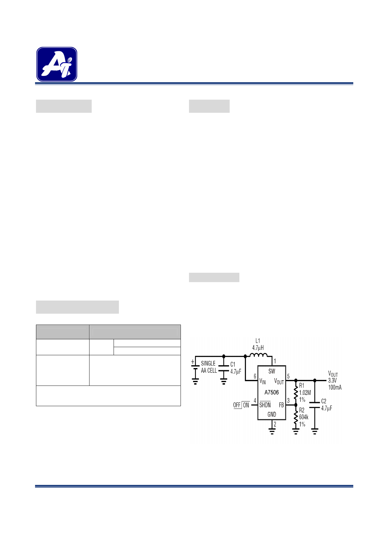
Typical Application Circuit
REV1.0 - APR 2009 RELEASED -
Fig 1. A7506-ADJ
-1-
1 page 
AiT Semiconductor Inc.
www.ait-ic.com
A7506
600mA, 1.2MHz CONSTANT FREQUENCY
SYNCHRONUS STEP-UP DC-DC CONVERTER
TYPICAL PERFORMANCE CHARACTERISTICS
1. Efficiency vs. Output Current
VOUT=3.3V, TA=25℃
2. Efficiency vs. Output Current
VOUT=5.0V, TA=25℃
3. Output Voltage vs. Output Current
VOUT=3.3V, TA=25℃
4. Output Voltage vs. Output Current
VOUT=5.0V, TA=25℃
5. Minimum Start-Up Voltage vs. Output Current
VOUT=3.3V, TA=25℃
6. Maximum Start-Up Voltage vs. Output Current
VOUT=3.3V, TA=25℃
REV1.0 - APR 2009 RELEASED -
-5-
5 Page 
AiT Semiconductor Inc.
www.ait-ic.com
A7506
600mA, 1.2MHz CONSTANT FREQUENCY
SYNCHRONUS STEP-UP DC-DC CONVERTER
Input Capacitor Selection
The input capacitor reduces the surge current drawn from the input and switching noise from the device. A
minimum 4.7µF input capacitor is needed for most applications. The input capacitor impedance at the switching
frequency should be less than input source impedance to prevent high frequency switching current passing to the
input. A low ESR input capacitor sized for maximum RMS current must be used. Ceramic capacitors with X5R
or X7R dielectrics are highly recommended because of their low ESR and small temperature coefficients.
Output Diode Selection
An Shottky diode should be included when the output voltage is above 4.5V. The Schottky diode is optional for
the output voltage not more than 4.5V, but can improve efficiency by about 2% to 3%.
PCB Layout Guidance
The A7506 operates at 1.2MHz typically. This is a considerably high frequency for dc-dc converters. In such case
PCB layout is important to guarantee satisfactory performance. It is recommended to make traces of the power
loop, especially where switching node is involved as short and wide as possible. First of all, the inductor, input
and output capacitor should be close to the device. Feedback and shut down circuit should avoid the proximity of
large AC signals, e.g. the power inductor and switching nodes. The optional rectifier diode (D1) can improve
efficiency and alleviate the stress on the integrated MOSFET. The diode should also be close to the inductor and
the chip to form the shortest possible switching loop. While 2 layer PCB shown in Fig.4 is enough for most
applications. Large and integral multi layer ground planes are ideal for high power applications. Large area of
copper has lower resistance and helps to dissipate heat on the device. The converter’s ground should join the
system ground to which it supplies power at one point only. Below is an example PCB layout for A7506.
REV1.0 - APR 2009 RELEASED -
- 11 -
11 Page | ||
| Páginas | Total 13 Páginas | |
| PDF Descargar | [ Datasheet A7506.PDF ] | |
Hoja de datos destacado
| Número de pieza | Descripción | Fabricantes |
| A7501 | 300KHz PFM STEP-UP DC-DC CONVERTER | AiT Semiconductor |
| A7506 | 1.2MHz CONSTANT FREQUENCY SYNCHRONUS STEP-UP DC-DC CONVERTER | AiT Semiconductor |
| A7508 | 1.3MHz MICROPOWER SYNCHRONOUS DC-DC CONVERTER BOOST | AiT Semiconductor |
| Número de pieza | Descripción | Fabricantes |
| SLA6805M | High Voltage 3 phase Motor Driver IC. |
Sanken |
| SDC1742 | 12- and 14-Bit Hybrid Synchro / Resolver-to-Digital Converters. |
Analog Devices |
|
DataSheet.es es una pagina web que funciona como un repositorio de manuales o hoja de datos de muchos de los productos más populares, |
| DataSheet.es | 2020 | Privacy Policy | Contacto | Buscar |