|
|
|
PDF ITS436L2S Data sheet ( Hoja de datos )
| Número de pieza | ITS436L2S | |
| Descripción | Smart High-Side Power Switch | |
| Fabricantes | Infineon | |
| Logotipo | ||
Hay una vista previa y un enlace de descarga de ITS436L2S (archivo pdf) en la parte inferior de esta página. Total 12 Páginas | ||
|
No Preview Available !
PROFET® ITS436L2
Smart High-Side Power Switch
for Industrial Applications
One Channel: 38mΩ
Status Feedback
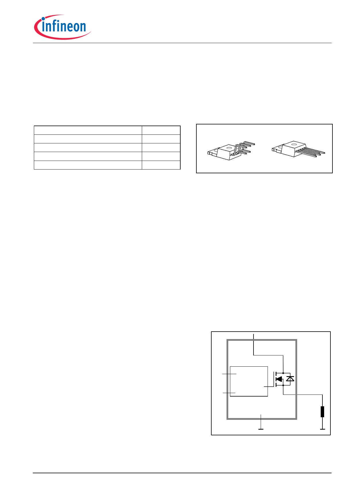
Product Summary
Package
On-state Resistance
Operating Voltage
Nominal load current
Current limitation
Operating Temperature
RON
Vbb(on)
IL(NOM)
IL(SCr)
Ta
38mΩ
4.75...41V
9.8A
40A
-30 …+85°C
PG-TO220-5-11
PG-TO220-5-12
Standard
Straight
General Description
• N channel vertical power MOSFET with charge pump, ground referenced CMOS compatible input and
diagnostic feedback, monolithically integrated in Smart SIPMOS technology.
• Providing embedded protective functions
Applications
• µC compatible high-side power switch with diagnostic feedback for 5V, 12V and 24V grounded loads in
industrial applications
• All types of resistive, inductive and capacitve loads
• Most suitable for loads with high inrush currents, so as lamps
• Replaces electromechanical relays, fuses and discrete circuits
Basic Functions
• Very low standby current
• CMOS compatible input
• Fast demagnetization of inductive loads
• Stable behaviour at undervoltage
• Wide operating voltage range
• Logic ground independent from load ground
Protection Functions
• Short circuit protection
• Overload protection
• Current limitation
• Thermal shutdown
• Overvoltage protection (including load dump) with external
resistor
• Reverse battery protection with external resistor
• Loss of ground and loss of Vbb protection
• Electrostatic discharge protection (ESD)
Block Diagram
Vbb
IN Logic
with
protection
ST functions
OUT
Diagnostic Function
• Diagnostic feedback with open drain output
• Open load detection in ON-state
• Feedback of thermal shutdown in ON-state
PROFET
GND
Load
Infineon Technologies AG
Page 1
2006-Mar-28
1 page 
Parameter and Conditions
at Tj =-40...+150°C, Vbb = 12 V unless otherwise specified
Protection Functions10)
Current limit (pin 3 to 5)
(see timing diagrams on page 11)
Tj =-40°C:
Tj =25°C:
Tj =+150°C:
Repetitive short circuit shutdown current limit
Tj = Tjt (see timing diagrams, page 11)
Thermal shutdown time11)
Tj,start = 25°C:
(see timing diagrams on page 11)
Output clamp (inductive load switch off)
at VOUT = Vbb - VON(CL)
IL= 40 mA:
Thermal overload trip temperature
Thermal hysteresis
Reverse battery (pin 3 to 1) 12)
Reverse battery voltage drop (Vout > Vbb)13 )
IL = -2 A
Tj=150 °C:
Symbol
IL(lim)
IL(SCr)
toff(SC)
VON(CL)
Tjt
∆Tjt
-Vbb
-VON(rev)
Diagnostic Characteristics
Open load detection current
(on-condition)
IL (OL)
Input and Status Feedback14)
Input resistance
see circuit page 7
Input turn-on threshold voltage
Input turn-off threshold voltage
Input threshold hysteresis
Off state input current (pin 2), VIN = 0.4 V
On state input current (pin 2), VIN = 5 V
Delay time for status with open load after switch off
(see timing diagrams on page 11)
Status output (open drain)
Zener limit voltage
ST low voltage
IST = +1.6 mA:
IST = +1.6 mA:
RI
VIN(T+)
VIN(T-)
∆ VIN(T)
IIN(off)
IIN(on)
td(ST OL4)
VST(high)
VST(low)
PROFET® ITS436L2
Values
Unit
min typ max
46 58
39 51
30 38
-- 40
-- 1.9
41
43 47
150 --
-- 10
-- --
-- 600
68 A
58
46
-- A
-- ms
52 V
-- °C
-- K
32 V
-- mV
100 -- 900 mA
2.5 3.5
1.7 --
1.5 --
-- 0.5
1 --
20 50
100 520
6 kΩ
3.2 V
-- V
-- V
50 µA
90 µA
900 µs
5.4 6.1
-- --
-- V
0.4
10) Integrated protection functions are designed to prevent IC destruction under fault conditions described in the
data sheet. Fault conditions are considered as "outside" normal operating range. Protection functions are
not designed for continuous repetitive operation.
11) Device on 50mm*50mm*1.5mm epoxy PCB FR4 with 6cm2 (one layer, 70µm thick) copper area for Vbb
connection. PCB is vertical without blown air.
12) Requires 150 Ω resistor in GND connection. The reverse load current through the intrinsic drain-source
diode has to be limited by the connected load. Note that the power dissipation is higher compared to normal
operating conditions due to the voltage drop across the intrinsic drain-source diode. The temperature
protection is not active during reverse current operation! Input and Status currents have to be limited (see
max. ratings page 3 and circuit page 7).
13) not subject to production test, specified by design
14) If a ground resistor RGND is used, add the voltage drop across this resistor.
Infineon Technologies AG
Page 5
2006-Mar-28
5 Page 
Figure 3a: Short circuit
shut down by overtemperature, reset by cooling
IN other channel: normal operation
IL
I L(lim)
I L(SCr)
PROFET® ITS436L2
Figure 5a: Open load: detection in ON-state, open
load occurs in on-state
IN
td(ST OL)
ST
t d(ST OL)
VOUT
t off(SC)
ST
IL normal
open
normal
t
Heating up of the chip may require several milliseconds, depending
on external conditions
td(ST OL) = 10 µs typ.
Figure 4a: Overtemperature:
Reset if Tj <Tjt
IN
Figure 5b: Open load: turn on/off to open load
IN
t
ST td(STOL4)
ST
V
OUT
I
L
T
J
t
t
Infineon Technologies AG
Page 11
2006-Mar-28
11 Page | ||
| Páginas | Total 12 Páginas | |
| PDF Descargar | [ Datasheet ITS436L2S.PDF ] | |
Hoja de datos destacado
| Número de pieza | Descripción | Fabricantes |
| ITS436L2 | Smart High-Side Power Switch | Infineon |
| ITS436L2S | Smart High-Side Power Switch | Infineon |
| Número de pieza | Descripción | Fabricantes |
| SLA6805M | High Voltage 3 phase Motor Driver IC. |
Sanken |
| SDC1742 | 12- and 14-Bit Hybrid Synchro / Resolver-to-Digital Converters. |
Analog Devices |
|
DataSheet.es es una pagina web que funciona como un repositorio de manuales o hoja de datos de muchos de los productos más populares, |
| DataSheet.es | 2020 | Privacy Policy | Contacto | Buscar |