|
|
|
PDF MRFE6VP100HR5 Data sheet ( Hoja de datos )
| Número de pieza | MRFE6VP100HR5 | |
| Descripción | RF Power LDMOS Transistors | |
| Fabricantes | Freescale Semiconductor | |
| Logotipo | ||
Hay una vista previa y un enlace de descarga de MRFE6VP100HR5 (archivo pdf) en la parte inferior de esta página. Total 20 Páginas | ||
|
No Preview Available !
Freescale Semiconductor
Technical Data
RF Power LDMOS Transistors
High Ruggedness N--Channel
Enhancement--Mode Lateral MOSFETs
RF power transistors designed for both narrowband and broadband ISM,
broadcast and aerospace applications operating at frequencies from 1.8 to
2000 MHz. These devices are fabricated using Freescale’s enhanced
ruggedness platform and are suitable for use in applications where high VSWRs
are encountered.
Typical Performance: VDD = 50 Volts
Frequency
(MHz)
Signal Type
Pout
(W)
Gps
(dB)
ηD IMD
(%) (dBc)
30--512 (1,3)
Two--Tone
(100 kHz spacing)
100 PEP
19.0
30.0
--30
512 (2)
CW
100
27.2 70.0
—
512 (2)
Pulse (200 μsec, 20% 100 Peak
Duty Cycle)
26.0
70.0
—
Load Mismatch/Ruggedness
Frequency
(MHz)
Signal Type
VSWR
Pout
(W)
Test
Voltage
Result
512 (2)
Pulse
>65:1
130
50 No Device
(100 μsec, 20% at all Phase (3 dB
Degradation
Duty Cycle)
Angles Overdrive)
512 (2)
CW
126
(3 dB
Overdrive)
1. Measured in 30--512 MHz broadband reference circuit.
2. Measured in 512 MHz narrowband test circuit.
3. The values shown are the minimum measured performance numbers across the
indicated frequency range.
Features
• Wide Operating Frequency Range
• Extremely Rugged
• Unmatched, Capable of Very Broadband Operation
• Integrated Stability Enhancements
• Low Thermal Resistance
• Integrated ESD Protection Circuitry
• In Tape and Reel. R5 Suffix = 50 Units, 56 mm Tape Width, 13 inch Reel.
Document Number: MRFE6VP100H
Rev. 0, 5/2012
MRFE6VP100HR5
MRFE6VP100HSR5
1.8--2000 MHz, 100 W, 50 V
BROADBAND
RF POWER LDMOS TRANSISTORS
NI--780--4
MRFE6VP100HR5
NI--780S--4
MRFE6VP100HSR5
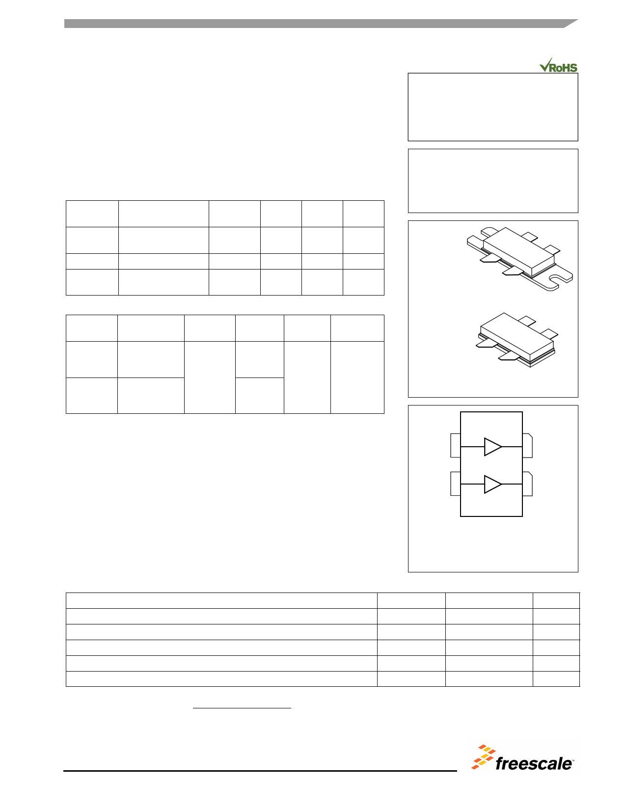
Gate A
Drain A
Gate B
Drain B
(Top View)
Note: The backside of the package is the
source terminal for the transistor.
Figure 1. Pin Connections
Table 1. Maximum Ratings
Rating
Symbol
Value
Unit
Drain--Source Voltage
VDSS
--0.5, +133
Vdc
Gate--Source Voltage
VGS
--6.0, +10
Vdc
Storage Temperature Range
Tstg
--65 to +150
°C
Case Operating Temperature
TC
--40 to +150
°C
Operating Junction Temperature (4,5)
TJ
--40 to +225
°C
4. Continuous use at maximum temperature will affect MTTF.
5. MTTF calculator available at http://www.freescale.com/rf. Select Software & Tools/Development Tools/Calculators to access MTTF
calculators by product.
© Freescale Semiconductor, Inc., 2012. All rights reserved.
RF Device Data
Freescale Semiconductor, Inc.
MRFE6VP100HR5 MRFE6VP100HSR5
1
1 page 
RF Device Data
Freescale Semiconductor, Inc.
MRFE6VP100HR5 MRFE6VP100HSR5
5
5 Page 
TYPICAL CHARACTERISTICS — 30--512 MHz
BROADBAND REFERENCE CIRCUIT
28 210
26
24
VDD = 50 Vdc, Pin = 2 W
IDQ(A+B) = 100 mA
195
180
22 165
20
18 Pout
150
135
16 120
14
12 Gps
105
90
10 75
8 60
6 ηD
4
45
30
2 15
00
0 50 100 150 200 250 300 350 400 450 500 550
f, FREQUENCY (MHz)
Figure 13. Power Gain, CW Output Power and Drain
Efficiency versus Frequency at a Constant Input Power
200
VDD = 50 Vdc
Pin = 1 W
150
30 MHz
100
512 MHz
100 MHz
50
0
0 0.5 1 1.5 2 2.5 3 3.5 4
VGS, GATE--SOURCE VOLTAGE (VOLTS)
Figure 14. CW Output Power versus Gate--Source
Voltage at a Constant Input Power
200
VPDinD==25W0 Vdc
150
512 MHz
100
50
30 MHz
100 MHz
0
0 0.5 1 1.5 2 2.5 3 3.5 4
VGS, GATE--SOURCE VOLTAGE (VOLTS)
Figure 15. CW Output Power versus Gate--Source
Voltage at a Constant Input Power
RF Device Data
Freescale Semiconductor, Inc.
MRFE6VP100HR5 MRFE6VP100HSR5
11
11 Page | ||
| Páginas | Total 20 Páginas | |
| PDF Descargar | [ Datasheet MRFE6VP100HR5.PDF ] | |
Hoja de datos destacado
| Número de pieza | Descripción | Fabricantes |
| MRFE6VP100HR5 | RF Power LDMOS Transistors | Freescale Semiconductor |
| Número de pieza | Descripción | Fabricantes |
| SLA6805M | High Voltage 3 phase Motor Driver IC. |
Sanken |
| SDC1742 | 12- and 14-Bit Hybrid Synchro / Resolver-to-Digital Converters. |
Analog Devices |
|
DataSheet.es es una pagina web que funciona como un repositorio de manuales o hoja de datos de muchos de los productos más populares, |
| DataSheet.es | 2020 | Privacy Policy | Contacto | Buscar |