|
|
|
PDF 74HC14 Data sheet ( Hoja de datos )
| Número de pieza | 74HC14 | |
| Descripción | HEX INVERTERS | |
| Fabricantes | Diodes | |
| Logotipo | ||
 1. inverting Schmitt trigger - NXP Hay una vista previa y un enlace de descarga de 74HC14 (archivo pdf) en la parte inferior de esta página. Total 9 Páginas | ||
|
No Preview Available !
74HC14
HEX INVERTERS WITH SCHMITT TRIGGER INPUTS
Description
The 74HC14 provides provides six independent Schmitt trigger input
inverters with standard push-pull outputs. The device is designed for
operation with a power supply range of 2.0V to 6.0V.
The gates perform the Boolean function:
Y=A
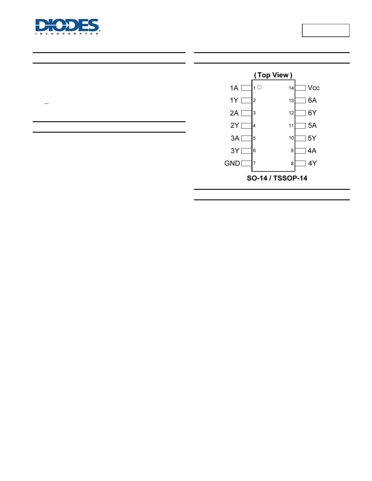
Pin Assignments
Features
• Wide Supply Voltage Range from 2.0V to 6.0V
• Sinks or Sources 4mA at VCC = 4.5V
• CMOS Low Power Consumption
• Schmitt Trigger Action at All Inputs
• ESD Protection Exceeds JESD 22
200-V Machine Model (A115-A)
2000-V Human Body Model (A114-A)
Exceeds 1000-V Charged Device Model (C101C)
• Range of Package Options SO-14 and TSSOP-14
• Totally Lead-Free & Fully RoHS Compliant (Notes 1 & 2)
• Halogen and Antimony Free. “Green” Device (Note 3)
Applications
• General Purpose Logic
• Wide array of products such as:
PCs, Networking, Notebooks, Netbooks
Computer Peripherals, Hard Drives, CD/DVD ROM
TV, DVD, DVR, Set Top Box
Notes:
1. No purposely added lead. Fully EU Directive 2002/95/EC (RoHS) & 2011/65/EU (RoHS 2) compliant.
2. See http://www.diodes.com for more information about Diodes Incorporated’s definitions of Halogen- and Antimony-free, "Green" and Lead-free.
3. Halogen- and Antimony-free "Green” products are defined as those which contain <900ppm bromine, <900ppm chlorine (<1500ppm total Br + Cl) and
<1000ppm antimony compounds.
74HC14
Document number: DS35323 Rev. 2 - 2
1 of 9
www.diodes.com
January 2013
© Diodes Incorporated
1 page 
Parameter Measurement Information
74HC14
Vcc
2.0V to 6.0V
Inputs
VI tr/tf
VCC 6ns
VM
VCC/2
CL
15pF, 50pF
Voltage Waveform
Pulse Duration
Voltage Waveform
Propagation Delay Times
Inverting and Non Inverting Outputs
Notes:
A. Includes test lead and test apparatus capacitance.
B. All pulses are supplied at pulse repetition rate ≤ 1 MHz
C. Inputs are measured separately one transition per measurement.
D. tPLH and tPHL are the same as tPD.
Figure 1 Load Circuit and Voltage Waveforms
74HC14
Document number: DS35323 Rev. 2 - 2
5 of 9
www.diodes.com
January 2013
© Diodes Incorporated
5 Page | ||
| Páginas | Total 9 Páginas | |
| PDF Descargar | [ Datasheet 74HC14.PDF ] | |
Hoja de datos destacado
| Número de pieza | Descripción | Fabricantes |
| 74HC10 | Triple 3-input NAND gate | Philips |
| 74HC107 | Dual JK flip-flop with reset negative-edge trigger | Philips |
| 74HC109 | Dual JK flip-flop with set and reset positive-edge trigger | Philips |
| 74HC11 | Triple 3-input AND gate | Philips |
| Número de pieza | Descripción | Fabricantes |
| SLA6805M | High Voltage 3 phase Motor Driver IC. |
Sanken |
| SDC1742 | 12- and 14-Bit Hybrid Synchro / Resolver-to-Digital Converters. |
Analog Devices |
|
DataSheet.es es una pagina web que funciona como un repositorio de manuales o hoja de datos de muchos de los productos más populares, |
| DataSheet.es | 2020 | Privacy Policy | Contacto | Buscar |