|
|
|
PDF ISL22511 Data sheet ( Hoja de datos )
| Número de pieza | ISL22511 | |
| Descripción | Single Push Button Controlled Potentiometer | |
| Fabricantes | Intersil | |
| Logotipo | ||
Hay una vista previa y un enlace de descarga de ISL22511 (archivo pdf) en la parte inferior de esta página. Total 13 Páginas | ||
|
No Preview Available !
ISL22511
Single Push Button Controlled Potentiometer (XDCP™)
Data Sheet
September 9, 2015
FN6678.2
Low Noise, Low Power, 32 Taps, Push
Button Controlled Potentiometer
The Intersil ISL22511 is a three-terminal digitally-controlled
potentiometer (XDCP) implemented by a resistor array
composed of 31 resistive elements and a wiper switching
network. The ISL22511 features a push button control, a
shutdown mode, as well as an industry-leading UTQFN
package.
The push button control has individual PU and PD inputs for
adjusting the wiper. To eliminate redundancy, the wiper
position will automatically increment or decrement if one of
these inputs is held longer than one second.
Forcing both PU and PD low for more than two seconds
activates shutdown mode. Shutdown mode disconnects the
top of the resistor chain and moves the wiper to the lowest
position, minimizing power consumption.
The three terminals accessing the resistor chain naturally
configure the ISL22511 as a voltage divider. A rheostat is
easily formed by floating an end terminal or connecting it to
the wiper.
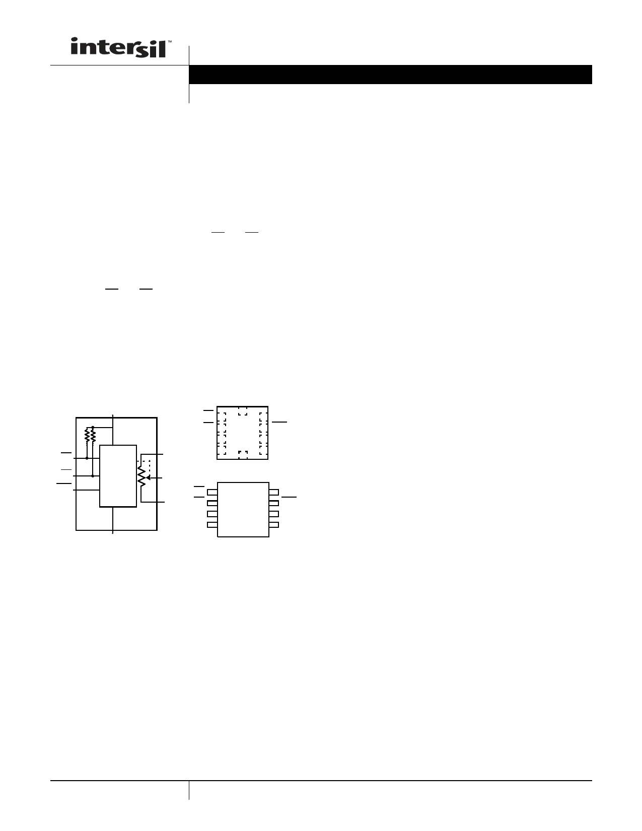
NC
VCC (SUPPLY VOLTAGE)
O
PU 1
9 VCC
PD 2 UTQFN 8 ASE
PU
PD
ASE
CONTROL
BLOCK
RH 3 (Top View) 7 RL
RH VSS 4
6 RW
NC
RW
O
PU 1
8 VCC
RL PD 2 SOIC 7 ASE
RH 3 (Top View) 6 RL
VSS 4
5 RW
VSS (GROUND)
Features
• Solid-State Non-Volatile Potentiometer
• Push Button Controlled
• Single or Auto Increment/Decrement
- Fast Mode after 1s Button Press
• AUTOSTORE of Last Wiper Position or Manual Store of
Wiper Position
• Shutdown Mode
• 32 Wiper Tap Points
- Middle Scale Wiper Position on Power-Up
• Low Power CMOS
- VCC = 2.7V to 5.5V
- Terminal Voltage, 0 to VCC
- Standby Current, 3µA Max
• RTOTAL Value = 10k50k
• High reliability
- Endurance: 1,000,000 data changes per bit per register
- Register data retention: 50 years @ T +55°C
• Packages
- 8 Ld SOIC
- 10 Ld UTQFN (2.1mmx1.6mm)
• Pb-Free (RoHS Compliant)
Applications
• Volume Control
• LED/LCD Brightness Control
• Contrast Control
• Programming Bias Voltages
• Ladder Networks
1
CAUTION: These devices are sensitive to electrostatic discharge; follow proper IC Handling Procedures.
1-888-INTERSIL or 1-888-468-3774 | Intersil (and design) is a registered trademark of Intersil Americas LLC
XDCP is a trademark of Intersil Americas Inc. Copyright Intersil Americas LLC 2008, 2009, 2015. All Rights Reserved
All other trademarks mentioned are the property of their respective owners.
1 page 
ISL22511
Potentiometer Specifications Over recommended operating conditions, unless otherwise specified. (Continued)
SYMBOL
PARAMETER
TEST CONDITIONS
MIN TYP MAX
(Note 18) (Note 5) (Note 18) UNIT
Roffset Offset
(Note 13)
W option
0 1 2 MI
(Note 12)
U option
0 0.5 1 MI
(Note 12)
DC Electrical Specifications Over recommended operating conditions unless otherwise specified.
SYMBOL
PARAMETER
TEST CONDITIONS
MIN TYP MAX
(Note 18) (Note 5) (Note 18)
ICC VCC Active Current
ICC VCC Current During Store Operation
VCC = 5.5V, perform wiper move
operation
VCC = 5.5V, perform non-volatile
store operation
150
2
ISB
ILkg
VIH
VIL
CIN
(Note 17)
Rpull_up
(Note 17)
Standby Current
PU, PD Input Leakage Current
PU, PD Input HIGH Voltage
PU, PD input LOW Voltage
PU, PD Input Capacitance
Pull-Up Resistor for PU and PD
0.6 3
VIN = VSS to VCC
-2 +2
VCC x 0.7
VCC x 0.1
VCC = 3.3V, TA = +25°C, f = 1MHz
10
1
EEPROM SPECIFICATIONS
EEPROM Endurance
1,000,000
EEPROM Retention
Temperature 55°C
50
UNIT
µA
mA
µA
µA
V
V
pF
M
Cycles
Years
5 FN6678.2
September 9, 2015
5 Page 
ISL22511
Shutdown Mode
The ISL22511 enters into Shutdown Mode if both PU and PD
inputs are kept LOW for 2 seconds. In this mode, the
resistors array is totally disconnected from its RH pin and the
wiper is moved to position closest to RL pin, as shown in
Figure 13. Note, that PU and PD inputs must be pulled LOW
within tDB time window of 15ms, see “Shutdown Mode
Timing” on page 7. Otherwise all command will be ignored till
both inputs will be released.
RH
Holding either PU, PD or ASE input LOW for more than
15ms will exit shutdown mode and return wiper to prior
shutdown position. If PU or PD will be held LOW for more
than 250ms, the ISL22511 will start auto-increment or
auto-decrement of wiper position.
RTOTAL with VCC Removed
The end to end resistance of the array will fluctuate once
VCC is removed.
RW
RL
FIGURE 13. DCP CONNECTION IN SHUTDOWN MODE
Revision History
The revision history provided is for informational purposes only and is believed to be accurate, but not warranted. Please go to the web to make
sure that you have the latest revision.
DATE
REVISION
CHANGE
September 9, 2015
FN6678.1
- Ordering Information Table on page 2.
- Added About Intersil Verbiage.
- Updated POD L10.2.1X1.6A to latest revision changes are as follow:
Updated to new POD format by removing table listing dimensions and moving dimensions onto drawing.
Added Typical Recommended Land Pattern. Removed package option.
- Updated POD M8.15 to latest revision changes are as follow:
Changed Note 1 "1982" to "1994"
Changed in Typical Recommended Land Pattern the following:
2.41(0.095) to 2.20(0.087)
0.76 (0.030) to 0.60(0.023)
0.200 to 5.20(0.205)
Updated to new POD format by removing table and moving dimensions onto drawing and adding land
pattern.
07/06/09
FN6678.1 Added reliability information on page 1 under Features and EEPROM Specifications in DC Electrical Spec
Table.
03/24/08
FN6678.0 Initial Release to web
About Intersil
Intersil Corporation is a leading provider of innovative power management and precision analog solutions. The company's products
address some of the largest markets within the industrial and infrastructure, mobile computing and high-end consumer markets.
For the most updated datasheet, application notes, related documentation and related parts, please see the respective product
information page found at www.intersil.com.
You may report errors or suggestions for improving this datasheet by visiting www.intersil.com/ask.
Reliability reports are also available from our website at www.intersil.com/support.
All Intersil U.S. products are manufactured, assembled and tested utilizing ISO9001 quality systems.
Intersil Corporation’s quality certifications can be viewed at www.intersil.com/design/quality
Intersil products are sold by description only. Intersil Corporation reserves the right to make changes in circuit design, software and/or specifications at any time without
notice. Accordingly, the reader is cautioned to verify that data sheets are current before placing orders. Information furnished by Intersil is believed to be accurate and
reliable. However, no responsibility is assumed by Intersil or its subsidiaries for its use; nor for any infringements of patents or other rights of third parties which may result
from its use. No license is granted by implication or otherwise under any patent or patent rights of Intersil or its subsidiaries.
For information regarding Intersil Corporation and its products, see www.intersil.com
11 FN6678.2
September 9, 2015
11 Page | ||
| Páginas | Total 13 Páginas | |
| PDF Descargar | [ Datasheet ISL22511.PDF ] | |
Hoja de datos destacado
| Número de pieza | Descripción | Fabricantes |
| ISL22511 | Single Push Button Controlled Potentiometer | Intersil |
| ISL22512 | Single Push Button Controlled Potentiometer | Intersil |
| Número de pieza | Descripción | Fabricantes |
| SLA6805M | High Voltage 3 phase Motor Driver IC. |
Sanken |
| SDC1742 | 12- and 14-Bit Hybrid Synchro / Resolver-to-Digital Converters. |
Analog Devices |
|
DataSheet.es es una pagina web que funciona como un repositorio de manuales o hoja de datos de muchos de los productos más populares, |
| DataSheet.es | 2020 | Privacy Policy | Contacto | Buscar |