|
|
|
PDF SM3470BB Data sheet ( Hoja de datos )
| Número de pieza | SM3470BB | |
| Descripción | Interpolation Encoder IC | |
| Fabricantes | NPC | |
| Logotipo | ||
Hay una vista previa y un enlace de descarga de SM3470BB (archivo pdf) en la parte inferior de esta página. Total 19 Páginas | ||
|
No Preview Available !
SM3470BB
Interpolation Encoder IC
OVERVIEW
The SM3470B is an interpolation IC for encoders. It accepts displacement detection, 2-phase analog signals (A and B phases) and a zero
point detection analog signal (Z phase) from an encoder, interpolates the signals by a specified interpolation factor, and outputs
corresponding 2-phase digital signals (A and B phases) and a zero point detection digital signal (Z phase). It incorporates a built-in
EEPROM for interpolation switching and input signal adjustment functions, providing support for system miniaturization and high-speed
input/output signal operation.
FEATURES
▪ Interpolation switching function: ×1, 2, 4, 8, 16, 32, 5, 10, 20 (selectable)
▪Adjustment function: Offset adjustment
▪ Supply voltage: 2.7 to 5.5V
▪ Operating temperature range: –40 to +125°C
▪ Input frequency: 500kHz (max)
▪ Output frequency: 2.5MHz (max)
▪ Package: QFN24 (size: 4mm × 4mm)
ORDERING INFORMATION
Device
SM3470BB-G*1
Package
24 pin QFN
*1. “-G” option code lead-free package
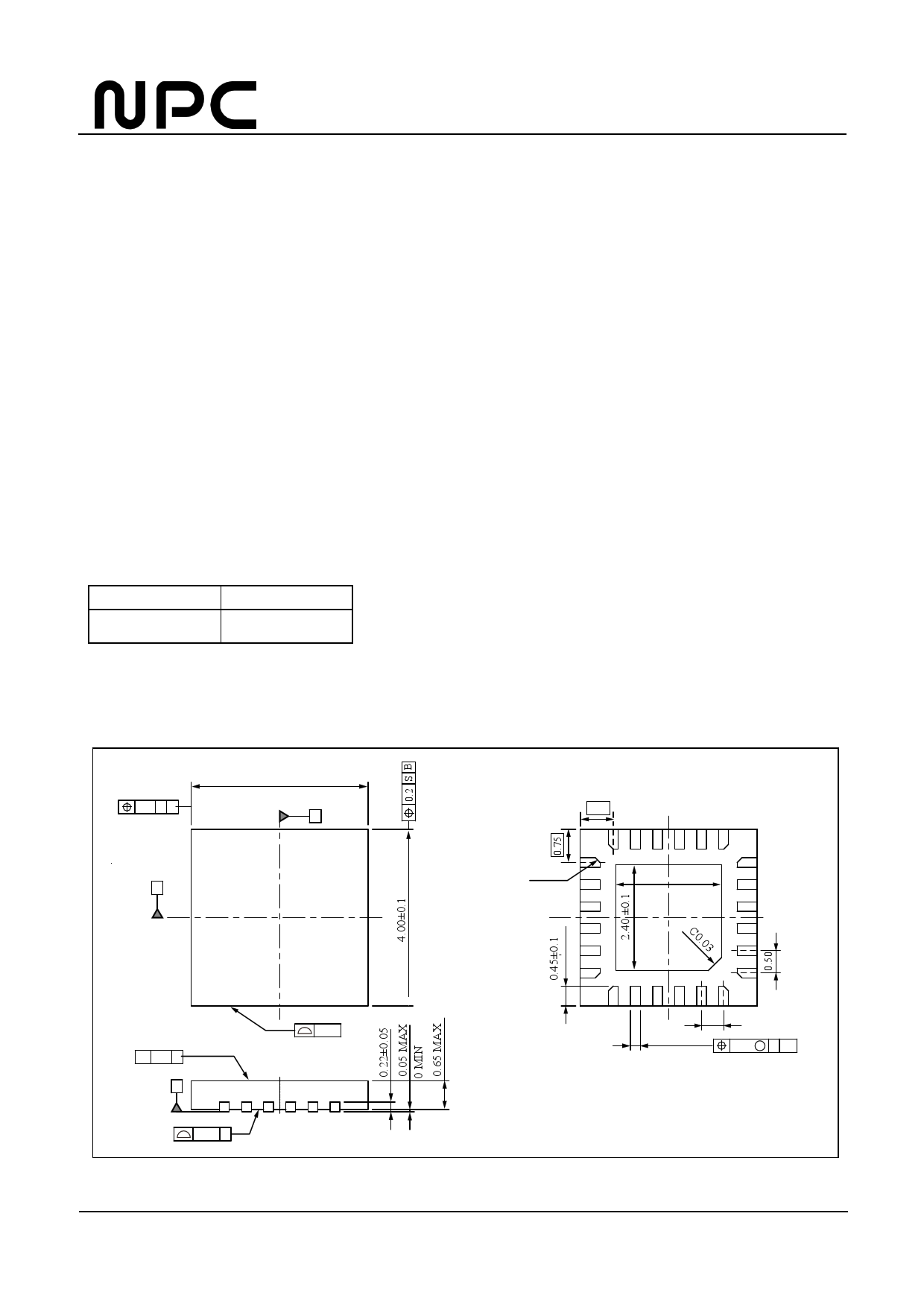
PACKAGE DIMENSIONS
0.2 S A
4.00±0.1
A
B
0.75
C0.11
2.40 ±0.1
// 0.2 S
S
0.08 S
0.15
0.50
0.22±0.05
0.05 M S AB
[unit:mm]
SEIKO NPC CORPORATION - 1
1 page 
SM3470BB
Analog Circuit Electrical Characteristics
Parameter
Symbol
VDD=2.7 to 5.5V, VSS=0V, Ta=–40 to +125°C unless otherwise noted
Conditions
Min Typ Max Unit
Input voltage range*1
VinHL
1
VDD–1
V
Output voltage*2
VoutH
VoutL
Iout = +1.5mA, digital output
Iout = –1.5mA, digital output
VDD–0.4
V
0.3 V
Input frequency
fin
500 kHz
Output frequency
fout
2.5 MHz
Angular error*3
(max – min)
VDD=5.0V, 16x interpolation,
ARAL
10kHz input frequency,
single-ended input,
3.0Vpp input amplitude
3 Degrees
Rise/Fall time
trf 0.1VDD to 0.9VDD, CL=20pF
10 ns
*1. A, AN, B, BN, Z, and ZN terminals.
*2. DA, DB, DZ, IO1, IO2, and IO3 terminals.
*3. The angular error expresses the variation from the ideal phase difference of interpolation outputs DA and DB as a phase difference of the input period.
Converting 3° and expressing as a percentage of the output period gives 13.3% using equation (1) below.
3 deg× 16 x
360 deg
= 13.3%
(1)
(where 16x is the interpolation factor)
SEIKO NPC CORPORATION - 5
5 Page 
Power-ON Timing
SM3470BB
VDD
EEPROM
Function
Output
(DA,DB,DZ)
Power On Reset release
EEPROM
ALL-DATA READ
DATA
Verify
NG
OK
Output disable
Hi-Z
Output enable
When power is applied, the settings written in EEPROM and the adjustment data are automatically transferred to the register. During this
interval, the outputs are disabled (Hi-Z). If there is a discrepancy between the data written to the resister and the EEPROM data after data
verification, the EEPROM settings are automatically transferred again and then the outputs are enabled if the data matches. The automatic
transfer time is 200µs or less. During this interval, the VPP terminal should be left open. If a voltage is applied to VPP, the automatic
transfer of settings is aborted.
Serial Interface
The IC has a built-in EEPROM for the register for the analog circuit adjustment and operating mode settings, and for data retention. The
EEPROM is accessed using a 3-wire serial interface.
The CE, CLK, and DATA signal inputs are used only when writing and reading data, and should not be modified at other times to prevent
incorrect operation.
The serial interface is disabled during the interval while the settings are automatically transferred from EEPROM to the register after power
is applied.
Data Format
CE
CLK
DATA
1 2 3 4 5 6 7 8 9 10 11 12 13 14 15 16
R/W R/E A2 A1 A0 D8 D7 D6 D5 D4 D3 D2 D1 D0
Read/Write
L: Read
H: Write
Address
Access destination: Register/EEPROM
L: Register
H: EEPROM
Data
* The read and write data are not guaranteed if there are too many or too few CLK pulses.
* Control the EEPROM data write time using the HIGH-level pulse time of the 15th and 16th pulses on CLK.
* The operating mode setting is ignored when writing to EEPROM. The mode is set when writing to the register.
SEIKO NPC CORPORATION - 11
11 Page | ||
| Páginas | Total 19 Páginas | |
| PDF Descargar | [ Datasheet SM3470BB.PDF ] | |
Hoja de datos destacado
| Número de pieza | Descripción | Fabricantes |
| SM3470BB | Interpolation Encoder IC | NPC |
| Número de pieza | Descripción | Fabricantes |
| SLA6805M | High Voltage 3 phase Motor Driver IC. |
Sanken |
| SDC1742 | 12- and 14-Bit Hybrid Synchro / Resolver-to-Digital Converters. |
Analog Devices |
|
DataSheet.es es una pagina web que funciona como un repositorio de manuales o hoja de datos de muchos de los productos más populares, |
| DataSheet.es | 2020 | Privacy Policy | Contacto | Buscar |