|
|
|
PDF EL7516 Data sheet ( Hoja de datos )
| Número de pieza | EL7516 | |
| Descripción | 600kHz/1.2MHz PWM Step-Up Regulator | |
| Fabricantes | Intersil | |
| Logotipo | ||
Hay una vista previa y un enlace de descarga de EL7516 (archivo pdf) en la parte inferior de esta página. Total 12 Páginas | ||
|
No Preview Available !
NOTPIRNECCOOMMPMAETNIBDILSEEL®D9R7FE5OP1R6LANDCEaEWtMaDESENhSTeIGeIStNS
600kHz/1.2MHz PWM Step-Up Regulator
The EL7516 is a high frequency, high efficiency step-up
voltage regulator operated at constant frequency PWM
mode. With an internal 1.5A, 200mΩ MOSFET, it can deliver
up to 600mA output current at over 90% efficiency. The
selectable 600kHz and 1.2MHz allows smaller inductors and
faster transient response. An external compensation pin
gives the user greater flexibility in setting frequency
compensation allowing the use of low ESR Ceramic output
capacitors.
When shut down, it draws <10µA of current and can operate
down to 2.5V input supply. These features along with
1.2MHz switching frequency makes it an ideal device for
portable equipment and TFT-LCD displays.
The EL7516 is available in an 8 Ld MSOP package with a
maximum height of 1.1mm. The device is specified for
operation over the full -40°C to +85°C temperature range.
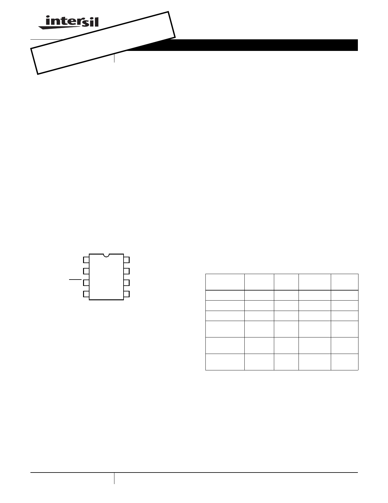
Pinout
EL7516
(8 LD MSOP)
TOP VIEW
COMP 1
FB 2
SHDN 3
GND 4
8 SS
7 FSEL
6 VDD
5 LX
October 9, 2007
EL7516
FN7333.6
Features
• >90% efficiency
• 1.6A, 200mΩ power MOSFET
• VIN > 2.5V
• 600kHz/1.2MHz switching frequency selection
• Adjustable soft-start
• Internal thermal protection
• 1.1mm max height 8 Ld MSOP package
• Pb-free plus anneal available (RoHS compliant)
Applications
• TFT-LCD displays
• DSL modems
• PCMCIA cards
• Digital cameras
• GSM/CDMA phones
• Portable equipment
• Handheld devices
Ordering Information
PART
NUMBER
PART TAPE &
PKG.
MARKING REEL PACKAGE DWG. #
EL7516IY
f
- 8 Ld MSOP MDP0043
EL7516IY-T7 f
7” 8 Ld MSOP MDP0043
EL7516IY-T13 f
13” 8 Ld MSOP MDP0043
EL7516IYZ
(Note)
BARAA
- 8 Ld MSOP MDP0043
(Pb-Free)
EL7516IYZ-T7 BARAA
(Note)
7” 8 Ld MSOP MDP0043
(Pb-Free)
EL7516IYZ-T13 BARAA
(Note)
13” 8 Ld MSOP MDP0043
(Pb-Free)
NOTE: Intersil Pb-free plus anneal products employ special Pb-free
material sets; molding compounds/die attach materials and 100%
matte tin plate termination finish, which are RoHS compliant and
compatible with both SnPb and Pb-free soldering operations. Intersil
Pb-free products are MSL classified at Pb-free peak reflow
temperatures that meet or exceed the Pb-free requirements of
IPC/JEDEC J STD-020.
1 CAUTION: These devices are sensitive to electrostatic discharge; follow proper IC Handling Procedures.
1-888-INTERSIL or 1-888-468-3774 | Intersil (and design) is a registered trademark of Intersil Americas Inc.
Copyright Intersil Americas Inc. 2002, 2004-2007. All Rights Reserved
All other trademarks mentioned are the property of their respective owners.
1 page 
EL7516
Typical Performance Curves (Continued)
90
85
80
75
0 100 200 300 400 500
IOUT (mA)
FIGURE 7. EFFICIENCY - 3.3V VIN TO 9V VOUT @ 600kHz
1.0
0.6
0.2
-0.2
-0.6
-1.0
0
100 200 300 400 500
IOUT (mA)
FIGURE 8. LOAD REGULATION - 3.3V VIN TO 9V VOUT
@ 600kHz
95
90
85
80
75
0 100 200 300 400 500 600
IOUT (mA)
FIGURE 9. EFFICIENCY - 5V VIN TO 12V VOUT @ 1.2MHz
0.8
0.6
0.4
0.2
1.0
-0.2
-0.4
-0.6
-0.8
-1
0
100 200 300 400 500 600
IOUT (mA)
FIGURE 10. LOAD REGULATION - 5V VIN TO 12V VOUT
@ 1.2MHz
92
90
88
86
84
0 100 200 300 400 500 600
IOUT (mA)
FIGURE 11. EFFICIENCY - 5V VIN TO 12V VOUT @ 600kHz
5
0.8
0.6
0.4
0.2
1.0
-0.2
-0.4
-0.6
-0.8
-1
0
100 200 300 400 500 600
IOUT (mA)
FIGURE 12. LOAD REGULATION - 5V VIN TO 12V VOUT
@ 600kHz
FN7333.6
October 9, 2007
5 Page 
EL7516
where:
IL = MOSFET current limit
IL-AVG = average inductor current
ΔIL = inductor ripple current
ΔIL = V-----I--N-L----×-×----[-(-(-V--V--O--O----+-+----V-V---D--D---I-IO--O---D-D---E-E---)-)---×-–----fV--S--I--N-----]
(EQ. 8)
VDIODE = Schottky diode forward voltage, typically, 0.6V
fS = switching frequency, 600kHz or 1.2MHz
IL-AVG
=
I--O-----U----T--
1–D
(EQ. 9)
D = MOSFET turn-on ratio:
D
=
1
–
------------------V----I--N--------------------
VOUT + VDIODE
(EQ. 10)
Table 1 gives typical maximum IOUT values for 1.2MHz
switching frequency and 22µH inductor:
VIN (V)
2.5
2.5
2.5
3.3
3.3
3.3
5
5
TABLE 1.
VOUT (V)
5
9
12
5
9
12
9
12
IOMAX (mA)
570
325
250
750
435
330
650
490
Thermal Performance
The EL7516 uses a fused-lead package, which has a
reduced θJA of 100°C/W on a four-layer board and 115°C/W
on a two-layer board. Maximizing copper around the ground
pins will improve the thermal performance.
This device also has internal thermal shut-down set at
around +130°C to protect the component.
Layout Considerations
To achieve highest efficiency, best regulation and the most
stable operation, a good printed circuit board layout is
essential. It is strongly recommended that the demoboard
layout be followed as closely as possible. Use the following
general guidelines when laying out the print circuit board:
1. Place C4 as close to the VDD pin as possible. C4 is the
supply bypass capacitor of the device.
2. Keep the C1 ground, GND pin and C2 ground as close as
possible.
3. Keep the two high current paths a) from C1 through L1, to
the LX pin and GND and b) from C1 through L1, D1, and
C2 as short as possible.
4. High current traces should be as short and as wide as
possible.
5. Place the feedback resistor close to the FB pin to avoid
noise pickup.
6. Place the compensation network close to the COMP pin.
The demo board is a good example of layout based on these
principles; it is available upon request.
Differences Between EL7516 and ISL97516
ISL97516 is the replacement for EL7516, and it is pin-to-pin
compatible to EL7516, but there are differences between the
two parts, as shown in the Table 2:
TABLE 2. DIFFERENCES BETWEEN EL7516 AND ISL97516
ISL97516
EL7516
Current Limit
2.0A (typical value) 1.5A (typical value)
Over-Temperature
Protection
+150°C
+130°C
Logic High or Low Level Refer to Ground,
Fixed.
Refer to input
voltage, Varying
From Table 2, it shows that ISL97516 can provide more
output current at the same conditions, and work in higher
ambient temperature. The fixed logic level also helps reduce
the system design complexity.
11 FN7333.6
October 9, 2007
11 Page | ||
| Páginas | Total 12 Páginas | |
| PDF Descargar | [ Datasheet EL7516.PDF ] | |
Hoja de datos destacado
| Número de pieza | Descripción | Fabricantes |
| EL7512 | High Frequency PWM Step-Up Regulator | Intersil Corporation |
| EL7512C | High Frequency PWM Step-Up Regulator | Elantec Semiconductor |
| EL7513 | White LED Step-Up Regulator | Intersil Corporation |
| EL7515 | High Frequency PWM Step-Up Regulator | Intersil Corporation |
| Número de pieza | Descripción | Fabricantes |
| SLA6805M | High Voltage 3 phase Motor Driver IC. |
Sanken |
| SDC1742 | 12- and 14-Bit Hybrid Synchro / Resolver-to-Digital Converters. |
Analog Devices |
|
DataSheet.es es una pagina web que funciona como un repositorio de manuales o hoja de datos de muchos de los productos más populares, |
| DataSheet.es | 2020 | Privacy Policy | Contacto | Buscar |