|
|
|
PDF ISL8273M Data sheet ( Hoja de datos )
| Número de pieza | ISL8273M | |
| Descripción | 80A Single Channel Digital PMBus Step-Down Power Module | |
| Fabricantes | Intersil | |
| Logotipo | ||
Hay una vista previa y un enlace de descarga de ISL8273M (archivo pdf) en la parte inferior de esta página. Total 30 Páginas | ||
|
No Preview Available !
DATASHEET
80A Single Channel Digital PMBus Step-Down Power
Module
ISL8273M
The ISL8273M is a complete PMBus enabled DC/DC single
channel step-down advance power supply capable of delivering
up to 80A of current and optimized for high power density
applications. For higher output current, up to four ISL8273Ms
can be paralleled to supply up to 320A in a multiphase current
sharing configuration.
Operating over an input voltage range of 4.5V to 14V, the
ISL8273M offers adjustable output voltages down to 0.6V and
achieves up to 93% conversion efficiencies. A unique
ChargeMode™ control architecture provides a single clock cycle
response to an output load step and can support switching
frequencies up to 1MHz. The power module integrates all power
and most passive components and only requires a few external
components to operate. A set of optional external resistors allows
the user to easily configure the device for standard operation. For
advanced configurations, a standard PMBus interface addresses
such things as sequencing and fault management, as well as
real-time full telemetry and point-of-load monitoring. Additionally,
an on-board nonvolatile memory can store the desired custom
configuration and settings.
A fully customizable voltage, current and temperature
protection scheme insures safe operation for the ISL8273M
under abnormal operating conditions. The device is also
supported by the PowerNavigator™ software, a full digital
power train development environment.
The ISL8273M is available in a low profile compact
18mmx23mmx7.5mm fully encapsulated thermally enhanced
HDA package.
Applications
• Server, telecom, storage and datacom
• Industrial/ATE and networking equipment
• General purpose power for ASIC, FPGA, DSP and memory
Features
• Complete digital power supply
• 80A single channel output current
- 4.5V to 14V single rail input voltage
- Up to 93% efficiency
- Up to 320A/4 parallel modules capable solution
- Multiphase and current sharing operations (180°/22.5°
steps)
• Programmable output voltage
- 0.6V to 2.5V output voltage settings
- ±1% accuracy over line/load/temperature
• ChargeMode™ control loop architecture
- 296kHz to 1.06MHz fixed switching frequency operations
- No compensation required
- Fast single clock cycle transient response
• PMBus interface and/or pin-strap mode
- Fully programmable through PMBus
- Pin-strap mode for standard settings
- Real-time telemetry for VIN, VOUT, IOUT, temperature, duty
cycle and fSW
• Advanced soft-start/stop, sequencing and margining
• On-board nonvolatile memory
• Complete over/undervoltage, current and temperature
protections with fault logging
• PowerNavigator™ supported
• Thermally enhanced 18mmx23mmx7.5mm HDA package
Related Literature
• UG036, “ISL8273MEVAL1Z Evaluation Board User Guide”
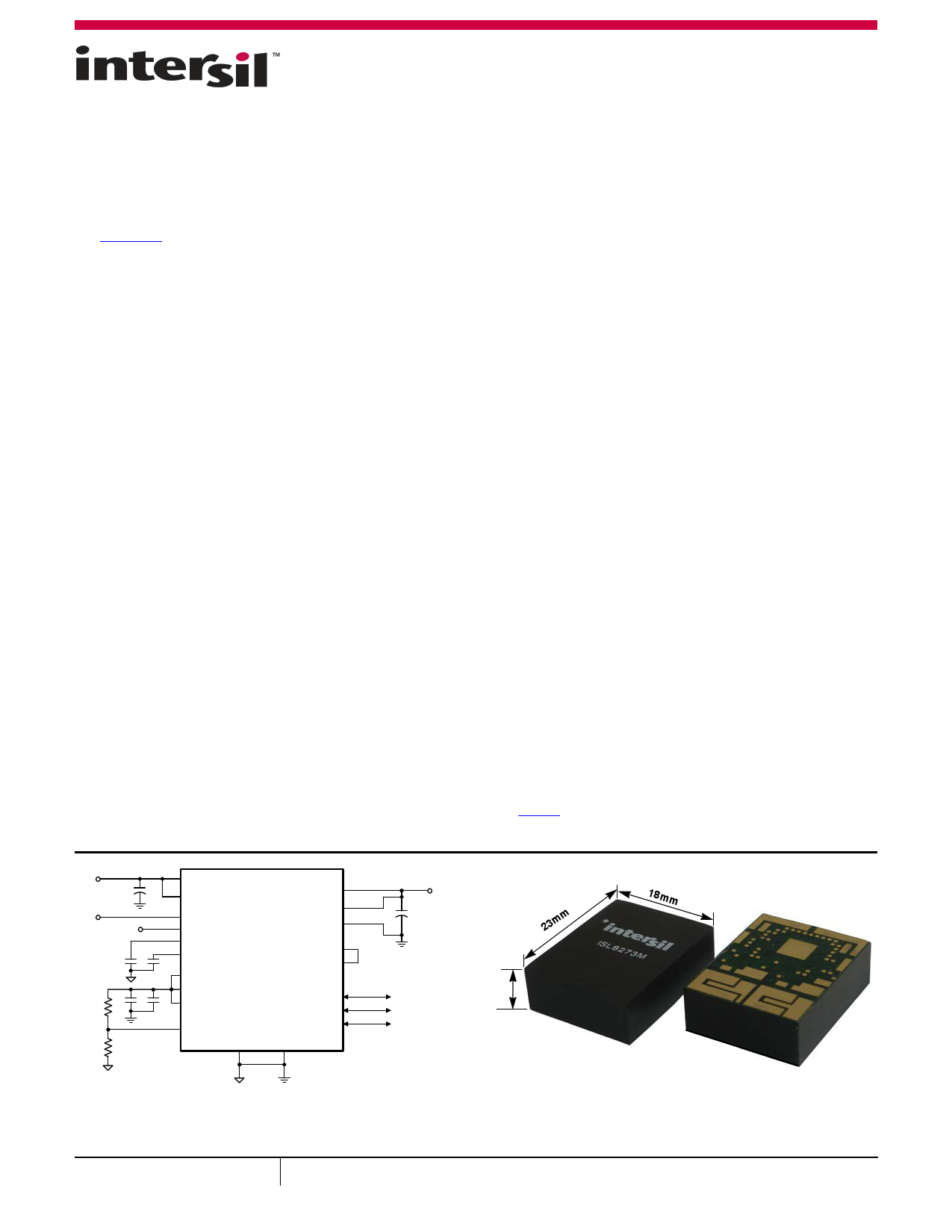
VIN
CIN
ENABLE
10µF 10µF
100k
2x10µF
6.65k
VIN
VDD
EN
PG
VR5
VR6
VDRV
VCC
VDRV1
VMON
ISL8273M
VOUT
VSENP
VSENN
VR
VR55
SGND
SCL
SDA
SALRT
PGND
VOUT
COUT
23mm
PMBUS
INTERFACE
7.5mm
18mm
NOTE: Figure 1 represents a typical implementation of the ISL8273M. For PMBus
operation, it is recommended to tie the enable pin (EN) to SGND.
FIGURE 1. 80A APPLICATION CIRCUIT
FIGURE 2. A SMALL PACKAGE FOR HIGH POWER DENSITY
September 10, 2015
FN8704.1
1
CAUTION: These devices are sensitive to electrostatic discharge; follow proper IC Handling Procedures.
1-888-INTERSIL or 1-888-468-3774 | Copyright Intersil Americas LLC 2015. All Rights Reserved
Intersil (and design), ChargeMode, PowerNavigator and Digital-DC are trademarks owned by Intersil Corporation
or one of its subsidiaries. All other trademarks mentioned are the property of their respective owners.
1 page 
ISL8273M
Pin Descriptions (Continued)
PIN
NUMBER
L2
L3
P11
L14
M1
M5, M17, N5
M10
M13
N6, N16
R8, R17
PIN
NAME
VR
SWD1
SWD2
VR5
VCC
PGND
VR55
VR6
VDRV
VDRV1
TYPE
DESCRIPTION
PWR Internal LDO bias pin. Tie VR to VR55 directly with a short loop trace. Not recommended to power external circuit.
PWR Switching node driving pins. Directly connect to the SW1 and SW2 pads with short loop wires.
PWR Internal 5V reference used to power internal circuitry. Place a 10µF decoupling capacitor for this pin. Maximum
external loading current is 5mA.
PWR Internal LDO output. Connect VCC to VDRV for internal LDO driving.
PWR Power grounds. Using multiple vias to connect the PGND pins to the internal PGND layer.
PWR Internal 5.5V bias voltage for internal LDO use only. Tie VR55 pin directly to the VR pin. Not recommended to power
external circuit.
PWR Internal 6V reference used to power internal circuitry. Place a 10µF decoupling capacitor for this pin. Not
recommended to power external circuit.
PWR Power supply for internal FET drivers. Connect a 10μF bypass capacitor to each of these pins. These pins can be
driven by the internal LDO through VCC pin or by the external power supply directly. Keep the driving voltage between
4.5V and 5.5V. For 5V input application, use external supply or connect this pin to VIN.
I Bias pin of the internal FET drivers. Always tie to VDRV.
Submit Document Feedback
5
FN8704.1
September 10, 2015
5 Page 
ISL8273M
Electrical Specifications VIN = VDD= 12V, fSW = 533kHz, TA = -40°C to +85°C, unless otherwise noted. Typical values are at
TA = +25°C. Boldface limits apply across the operating temperature range, -40°C to +85°C. (Continued)
SYMBOL
PARAMETER
TEST CONDITIONS
MIN
(Note 12)
TYP
MAX
(Note 12)
UNIT
IOUT_READ_RES Output Current Read Back Resolution
IOUT_RANGE
Output Current Range (Note 14)
IOUT_READ_ERR Output Current Read Back Total Error
SOFT-START AND SEQUENCING
PMBus read at max load. VOUT = 1V
0.087
±3
80
A
A
A
tON_DELAY
tON_DELAY_ACCY
tON_RISE
Delay Time from Enable to VOUT Rise
tON_DELAY Accuracy
Output Voltage Ramp-up Time
Configured using PMBus
Configured using PMBus. Single module
standalone
2
0.5
5000
ms
±2 ms
100 ms
tON_RISE_ACCY
Output Voltage Ramp-up Time
Accuracy
Single module standalone
±250
µs
tOFF_DELAY
tOFF_DELAY_ACCY
tOFF_FALL
Delay Time from Disable to VOUT Fall
tOFF_DELAY Accuracy
Output Voltage Fall Time
Configured using PMBus
Configured using PMBus. Single module
standalone
2
0.5
5000
ms
±2 ms
100 ms
tON_FALL_ACCY
POWER-GOOD
Output Voltage Fall Time Accuracy
Single module standalone
±250
µs
VPG_DELAY
Power-good Delay
TEMPERATURE SENSE
Configured using PMBus
0
5000
ms
TSENSE_RANGE Temperature Sense Range
Configurable via PMBus
-50
150 C
INT_TEMPACCY Internal Temperature Sensor Accuracy Tested at +100°C
-5 +5 C
FAULT PROTECTION
VDD_UVLO_RANGE
VDD_UVLO_ACCY
VDD Undervoltage Threshold Range
VDD Undervoltage Threshold Accuracy
(Note 15)
Measured internally
4.18
±2
16 V
%FS
VDD_UVLO_DELAY
VOUT_OV_RANGE
VDD Undervoltage Response Time
VOUT Overvoltage Threshold Range
VOUT_UV_RANGE VOUT Undervoltage Threshold Range
VOUT_OV/UV_ACCY VOUT OV/UV Threshold Accuracy
(Note 13)
Factory default
Configured using PMBus
Factory default
Configured using PMBus
10
1.15VOUT
1.05VOUT
VOUT_MAX
0.85VOUT
0 0.95VOUT
-2 +2
µs
V
V
V
V
%
VOUT_OV/UV_DELAY
ILIMIT_ACCY
VOUT OV/UV Response Time
Output Current Limit Set-point
Accuracy (Note 15)
Tested at IOUT_OC_FAULT_LIMIT = 80A
10
±10
µs
% FS
ILIMIT_DELAY
Output Current Fault Response Time Factory default
3 tSW
(Note 16)
TJUNCTION
Over-temperature Protection Threshold Factory default
(Controller Junction Temperature)
Configured using PMBus
125
-40 125
C
C
TJUNCTION_HYS Thermal Protection Hysteresis
15 C
Submit Document Feedback 11
FN8704.1
September 10, 2015
11 Page | ||
| Páginas | Total 30 Páginas | |
| PDF Descargar | [ Datasheet ISL8273M.PDF ] | |
Hoja de datos destacado
| Número de pieza | Descripción | Fabricantes |
| ISL8273M | 80A Single Channel Digital PMBus Step-Down Power Module | Intersil |
| Número de pieza | Descripción | Fabricantes |
| SLA6805M | High Voltage 3 phase Motor Driver IC. |
Sanken |
| SDC1742 | 12- and 14-Bit Hybrid Synchro / Resolver-to-Digital Converters. |
Analog Devices |
|
DataSheet.es es una pagina web que funciona como un repositorio de manuales o hoja de datos de muchos de los productos más populares, |
| DataSheet.es | 2020 | Privacy Policy | Contacto | Buscar |