|
|
|
PDF BD57011GWL Data sheet ( Hoja de datos )
| Número de pieza | BD57011GWL | |
| Descripción | Wireless Power Receiver IC | |
| Fabricantes | ROHM Semiconductor | |
| Logotipo | ||
Hay una vista previa y un enlace de descarga de BD57011GWL (archivo pdf) en la parte inferior de esta página. Total 22 Páginas | ||
|
No Preview Available !
Datasheet
Wireless Power Consortium / Qi Compliant series
Wireless Power Receiver IC
BD57011GWL
General Description
BD57011GWL is stand-alone integrated IC for wireless
power receiver. The device is composed fully
synchronous rectifier circuit in low-impedance FETs, Qi
compliant packet controller, Adjustable low-dropout, and
open-drain output terminal to communicate the power
transmitter by amplitude modulation.
BD57011GWL applies to 5W-power mobile application
based on WPC ver. 1.1.
Features
■ Low Impedance FET in rectifier
■ High efficiency fully synchronous rectifier
■ Maximum Input Voltage is 20V
■ WPC / Qi Lower Power ver1.1 support
■ Adjustable voltage at low-dropout
■ Open-Drain output terminal for modulation
■ TX-RX coil Position Gap alarm
Applications
WPC compliant Device
■ Smart Phones
■ Cell Phones
■ Hand-held Mobile Devices
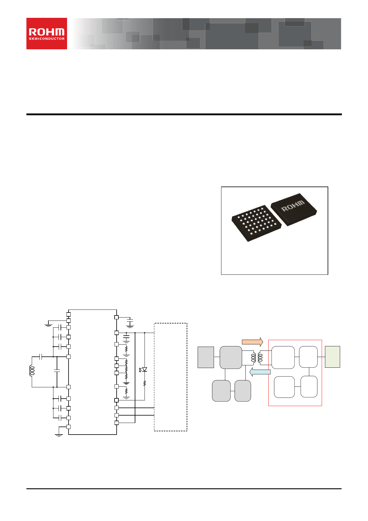
Typical Application Circuit
Key Specifications
■ Variable Output Voltage:
4.3~5.3V(16steps)
■ Maximum Input Voltage:
20[V] (Max.)
■ Maximum Input/Output Current:
1.1 [A] (Max.)
■ AC Input Frequency:
100-210 [kHz]
■ Operating Temperature Range: -20°C to +85°C
Package
W(Typ) D(Typ) H(Max)
UCSP50L3C
3.36 ㎜×2.62 ㎜×0.57 ㎜
(7 x 6 array, 0.4mm pitch)
ADGATE
ADDET
BOOT1
COMM1
CLAMP1
AC1
RECT
OUT
OUTSET
ILIM
FOD2
FOD
AC2
BOOT2
COMM2
CLAMP2
GND
POSSET
PG
CTRL
EN1
EN2
BD57011GWL
System
Load
(Charger
And
Battery)
Power
AC/DC
Half Bridge
Driver
BD57011GWL
Rectification
Voltage
Control
Feedback
Controller
Voltage
&
Current
Sensing
Qi packet
Controller
Voltage
&
Current
Sensing
Transmitter(TX)
Receiver(RX)
Load
Figure 1. Typical application circuit
Figure 2. Product position in Wireless
Power Supply System
○Product structure:Silicon monolithic integrated circuit
.www.rohm.com
© 2013 ROHM Co., Ltd. All rights reserved.
TSZ22111・14・001
○This product is not designed protection against radioactive rays
1/19
TSZ02201-0F2F0AK00110-1-2
2.Jul.2015 Rev.002
1 page 
BD57011GWL
Typical Performance Cures
5.05
5.04
5.03
5.02
5.01
5
4.99
4.98
4.97
4.96
4.95
-20.0
0.0
20.0 40.0 60.0 80.0
Temp [℃]
Figure 3. OUT Voltage [V] vs. Temp. [°C]
(ILIM=27k Ω)
8
7.5
7
RECT Voltage
6.5
6
5.5
5
4.5
4 OUT Voltage
3.5
3
0.0 0.1 0.2 0.3 0.4 0.5 0.6 0.7 0.8 0.9 1.0
Iload [A]
Figure 4. OUT Voltage [V] and RECT Voltage [V]
vs. Iload [A] (ILIM=27k Ω)
80
70
60
50
40
30
20
10
0
0.0 1.0 2.0 3.0 4.0 5.0
Output Power [W]
Figure 5. System Efficiency [%] vs. Output Power [W]
(ILIM=27k Ω)
Iload
RECT
OUT
Figure 6. Startup Waveform (ILIM=27k Ω)
www.rohm.com
© 2013 ROHM Co., Ltd. All rights reserved.
TSZ22111・15・001
5/19
TSZ02201-0F2F0AK00110-1-2
2.Jul.2015 Rev.002
5 Page 
BD57011GWL
9) FOD adjust setting
In order to implement FOD (Foreign Object Detection) function that Qi ver1.1 make rules, it is necessary to compute received
power strictly and to compare with the power transmitted power from the TX side. The FOD and FOD2 pin is used for the
received power fine tuning. These parameters adjust a lost (e.g. LC loss) which is not understood inside IC.
The relation between received power (PPR) and FOD, FOD2 pin input voltage becomes as the following formula.
PPR = α × f (RECT , IOUT ) + β[W ]
α = 1+ VFOD2 × 0.004
1.955mV
β = VFOD × 0.004 − 0.25[W ]
1.955mV
α is a parameter for slope adjust, proportional to FOD2 voltage. β is a parameter for offset adjust, proportional to FOD voltage.
A Function f(RECT, IOUT) is a value calculating in IC, nearly proportional to output power.
Setting example presents. It necessary to coordinated with RFOD, RFOD2 and ILIM setting resistor.
In the case of setting; ILIM=1A, α=1.2, β=0.1W, Solving the following simultaneous equations, the value of FOD setting resistors
is obtained.
RADJ = RLIM + RFOD2 + RFOD
(α −1) ×1.955mV = IILIM × (RFOD2 + RFOD)
0.004
(β + 0.25) ×1.955mV = IILIM × RFOD
0.004
In this case, RFOD=6.9kΩ, RFOD2=10.2kΩ,RLIM=82.9kΩ.
The configuration discribed above is a reference value. Must be adjusted by the considering external factors( the presence or
absence of the metal for absorbing the magnetic flux, such as a battery) and the surrounding environment of the coil material,
the coil shape, and the distance to the Tx coil.
10) POSSET setting
The height of the RECT voltage at a start-up is judged, and position gap of the XY direction between TX coil and RX coil is
detected. The threshold (Vth, pos) of whether to take out alarm with the resistance connected to a POSSET terminal can be
decided. When RECT voltage is lower than Vth,pos, a pulse is outputted 5 times from PG terminal at the time of an OUT output.
The relation between setting resistance and detection threshold voltage(Vth,pos) becomes as the following formula.
Vth, pos = 2.8 ×10⁵ [V ]
RPOS
RPOS is POSSET terminal connection resistance. E.g. Vth,pos=2.8V setup at the time of RPOS=100kΩ.
In the case of nullification for this function, set RPOS=120kΩ.
Coil-coupling strong
⇒No alarm
Vth,pos
RECT
voltage
Threshold voltage
adjustable using
external resistor
Coil-coupling weak
⇒Alarm output
VDD OUT
PG
PG
VDD
5 pulse output at OUT pin outputs.
www.rohm.com
© 2013 ROHM Co., Ltd. All rights reserved.
TSZ22111・15・001
Figure 12. Position Gap alarm
11/19
TSZ02201-0F2F0AK00110-1-2
2.Jul.2015 Rev.002
11 Page | ||
| Páginas | Total 22 Páginas | |
| PDF Descargar | [ Datasheet BD57011GWL.PDF ] | |
Hoja de datos destacado
| Número de pieza | Descripción | Fabricantes |
| BD57011GWL | Wireless Power Receiver IC | ROHM Semiconductor |
| Número de pieza | Descripción | Fabricantes |
| SLA6805M | High Voltage 3 phase Motor Driver IC. |
Sanken |
| SDC1742 | 12- and 14-Bit Hybrid Synchro / Resolver-to-Digital Converters. |
Analog Devices |
|
DataSheet.es es una pagina web que funciona como un repositorio de manuales o hoja de datos de muchos de los productos más populares, |
| DataSheet.es | 2020 | Privacy Policy | Contacto | Buscar |