|
|
|
PDF MSK4322 Data sheet ( Hoja de datos )
| Número de pieza | MSK4322 | |
| Descripción | SMART POWER 3-PHASE MOTOR DRIVE HYBRID | |
| Fabricantes | MSK | |
| Logotipo | ||
Hay una vista previa y un enlace de descarga de MSK4322 (archivo pdf) en la parte inferior de esta página. Total 7 Páginas | ||
|
No Preview Available !
MIL-PRF-38534 AND 38535 CERTIFIED FACILITY
20 AMP, 200 VOLT MOSFET
SMART POWER 3-PHASE
M.S. KENNEDY CORP.
MOTOR DRIVE HYBRID
4322
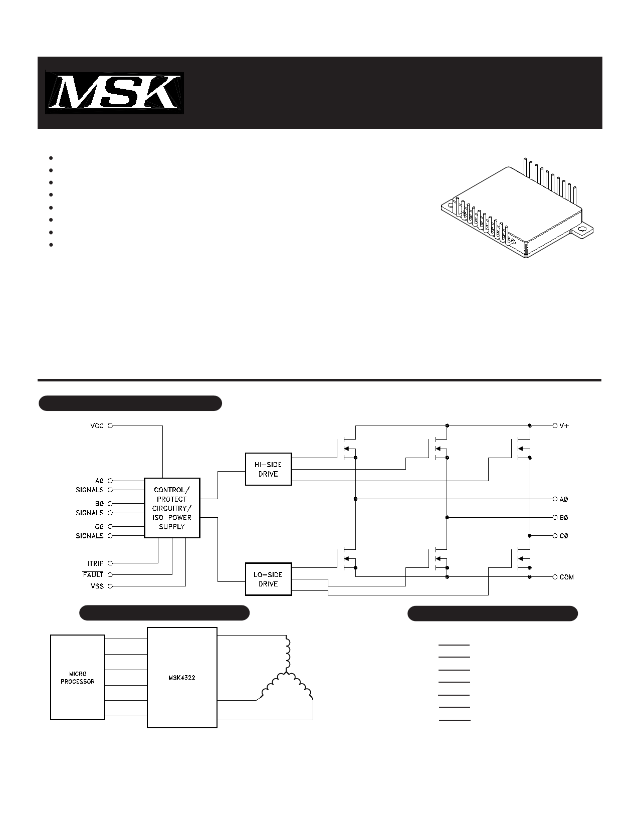
FEATURES:
200V, 20 Amp Capability
Ultra Low Thermal Resistance - Junction to Case - 0.6°C/W (Each MOSFET)
Self-Contained, Smart Lowside/Highside Drive Circuitry
Under-Voltage Lockout, Internal 2μS Deadtime
Capable of Switching Frequencies to 25KHz
Isolated Case Allows Direct Heat Sinking
Case Bolt-down Design Allows Superior Heat Dissipation
Contact MSK for MIL-PRF-38534 Qualification Status
DESCRIPTION:
The MSK4322 is a 20 Amp, 3 Phase Bridge Smart Power Motor Drive Hybrid with a 200 volt rating on the output switches.
The output switches are power MOSFETs with intrinsic fast-recovery diodes for the free-wheeling currents of motor drives.
This new smart power motor drive hybrid is compatible with 5V CMOS or TTL logic levels. The internal circuitry prevents
simultaneous turn-on of the in-line half bridge transistors with a built-in 2μS deadtime to prevent shoot-through. Undervoltage
lockout shuts down the bridge when the supply voltage gets to a point of incomplete turn-on of the output switches. The
internal high-side boot strap power supply derived from the +15 volt supply completely eliminates the need for 3 floating
independent power supplies for the high-side drive. Current sense circuitry is provided to sense current from an external
resistor to shut down the bridge for overcurrent.
EQUIVALENT SCHEMATIC
TYPICAL APPLICATIONS
TYPICAL APPLICATIONSPIN-OUT INFORMATION
3 PHASE SIX STEP DC BRUSHLESS MOTOR DRIVE
OR 3 PHASE SINUSOIDAL INDUCTION MOTOR DRIVE
1
PIN-OUT INFORMATION
1 VCC
2 AØHIN
3 BØHIN
4 CØHIN
5 AØLIN
6 FAULT
7 CØLIN
8 BØLIN
9 VSS
10 ITRIP
20 N/C
19 AØ
18 V+
17 N/C
16 N/C
15 BØ
14 N/C
13 N/C
12 CØ
11 COM
8548-67 Rev. J 12/14
1 page 
TYPICAL SYSTEM OPERATION
The MSK4322 is designed to be used with a +100 volt high voltage bus, +15 volt low power bus and +5 volt logic signals.
Proper derating should be applied when designing the MSK4322 into a system. High frequency layout techniques with ground
planes on a printed circuit board is the only method that should be used for circuit construction. This will prevent pulse jitter
caused by excessive noise pickup on the current sense signal or the error amp signal.
Ground planes for the low power circuitry and high power circuitry should be kept separate. The connection between the
bottom of the current sense resistor, VSS pin and the high power ground are connected at this point. This is a critical path and
high currents should not be flowing between the current sense and VSS. Inductance in this path should be kept to a minimum.
An RC filter (shown in 2 places) will filter out the current spikes and keep the detected noise for those circuits down to a
minimum.
In the system shown, two types of current limit are implemented. The first limit is a PWM pulse by pulse limit controlled by
the motor controller. A second absolute maximum limit is set up for the MSK4322 which will completely shut off the bridge in the
event that current limit is exceeded.
When controlling the motor speed by the PWM method, it is required that the low side switches be PWM pulsed
due to the bootstrap power supplies used to power the high side switch drives. The higher the PWM speed the higher the current
load on the drive supply. PWM of the low side will prevent sagging of the high side bootstrap supplies.
The logic signals coming from the typical motor controller IC are set up for driving N channel low side and P channel
high side switches directly and are usually 15 volt levels. Provision should be made for getting 5 volt logic signals to the
MSK4322 of the correct assertion levels. Typically, the low side signals out of the controller are high active and the high side are
low active. Inverters are shown in the system schematic for the low side controller output.
5 8548-67 Rev. J 12/14
5 Page | ||
| Páginas | Total 7 Páginas | |
| PDF Descargar | [ Datasheet MSK4322.PDF ] | |
Hoja de datos destacado
| Número de pieza | Descripción | Fabricantes |
| MSK4322 | MOTOR DRIVE POWER HYBRID | ETC |
| MSK4322 | SMART POWER 3-PHASE MOTOR DRIVE HYBRID | MSK |
| MSK4323 | SMART HIGH TEMP 3-PHASE MOTOR DRIVE HYBRID | MSK |
| Número de pieza | Descripción | Fabricantes |
| SLA6805M | High Voltage 3 phase Motor Driver IC. |
Sanken |
| SDC1742 | 12- and 14-Bit Hybrid Synchro / Resolver-to-Digital Converters. |
Analog Devices |
|
DataSheet.es es una pagina web que funciona como un repositorio de manuales o hoja de datos de muchos de los productos más populares, |
| DataSheet.es | 2020 | Privacy Policy | Contacto | Buscar |