|
|
|
PDF MMBT2222ALP4 Data sheet ( Hoja de datos )
| Número de pieza | MMBT2222ALP4 | |
| Descripción | NPN SMALL SIGNAL SURFACE MOUNT TRANSISTOR | |
| Fabricantes | Diodes | |
| Logotipo | ||
Hay una vista previa y un enlace de descarga de MMBT2222ALP4 (archivo pdf) en la parte inferior de esta página. Total 7 Páginas | ||
|
No Preview Available !
MMBT2222ALP4
40V NPN SMALL SIGNAL SURFACE MOUNT TRANSISTOR
Features
• Low Collector-Emitter Saturation Voltage, VCE(sat)
• Ultra-Small Leadless Surface Mount Package
• Totally Lead-Free & Fully RoHS Compliant (Notes 1 & 2)
• Halogen and Antimony Free. “Green” Device (Note 3)
• Qualified to AEC-Q101 Standards for High Reliability
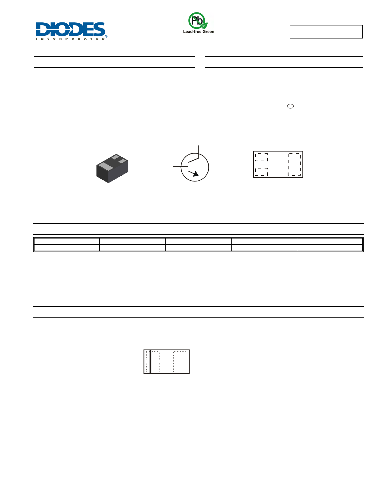
Mechanical Data
• Case: X2-DFN1006-3
• Case Material: Molded Plastic, "Green" Molding Compound.
UL Flammability Classification Rating 94V-0
• Moisture Sensitivity: Level 1 per J-STD-020
• Terminals: Finish ⎯ NiPdAu over Copper leadframe. Solderable
per MIL-STD-202, Method 208 e4
• Weight: 0.0009 grams (Approximate)
X2-DFN1006-3
Bottom View
C
B
E
Device Symbol
B
C
E
Top View
Device Schematic
Ordering Information (Note 4)
Product
MMBT2222ALP4-7B
Marking
2S
Reel size (inches)
7
Tape width (mm)
8
Quantity per reel
10,000
Notes:
1. No purposely added lead. Fully EU Directive 2002/95/EC (RoHS) & 2011/65/EU (RoHS 2) compliant.
2. See http://www.diodes.com for more information about Diodes Incorporated’s definitions of Halogen- and Antimony-free, "Green" and Lead-free.
3. Halogen- and Antimony-free "Green” products are defined as those which contain <900ppm bromine, <900ppm chlorine (<1500ppm total Br + Cl) and
<1000ppm antimony compounds.
4. For packaging details, go to our website at http://www.diodes.com.
Marking Information
2S
Top View
2S = Product Type Marking Code
Bar Denotes Base and Emitter Side
MMBT2222ALP4
Document number: DS35506 Rev. 3 - 2
1 of 7
www.diodes.com
August 2012
© Diodes Incorporated
1 page 
MMBT2222ALP4
1,000
TA = 125°C
100
TA = -25°C
TA = +25°C
10
1
0.1
1.0
VCE = 1.0V
1 10 100 1,000
IC, COLLECTOR CURRENT (mA)
Figure 4 Typical DC Current Gain vs.
Collector Current
0.9 VCE = 5V
0.8 TA = -50°C
0.7 TA = 25°C
0.6
0.5
TA = 150°C
0.4
0.3
0.2
0.1 1 10 100
IC, COLLECTOR CURRENT (mA)
Figure 6 Typical Base-Emitter Turn-On Voltage
vs. Collector Current
1,000
VCE = 5V
100
10
1
1 10 100
IC, COLLECTOR CURRENT (mA)
Figure 8 Typical Gain-Bandwidth Product vs. Collector Current
0.5
IC
IB = 10
0.4
0.3
0.2
TA = 25°C
TA = 150°C
0.1
TA = -50°C
0
1 10 100 1,000
IC, COLLECTOR CURRENT (mA)
Figure 5 Typical Collector-Emitter Saturation Voltage
vs. Collector Current
f = 1MHz
Cibo
Cobo
VR, REVERSE VOLTAGE (V)
Figure 7 Typical Capacitance Characteristics
2.0
1.8 IC = 1mA
IC = 30mA
1.6 IC = 10mA
IC = 100mA
1.4
1.2 IC = 300mA
1.0
0.8
0.6
0.4
0.2
0
0.001 0.01
0.1
1
10 100
IB, BASE CURRENT (mA)
Figure 9 Typical Collector Saturation Region
MMBT2222ALP4
Document number: DS35506 Rev. 3 - 2
5 of 7
www.diodes.com
August 2012
© Diodes Incorporated
5 Page | ||
| Páginas | Total 7 Páginas | |
| PDF Descargar | [ Datasheet MMBT2222ALP4.PDF ] | |
Hoja de datos destacado
| Número de pieza | Descripción | Fabricantes |
| MMBT2222ALP4 | NPN SMALL SIGNAL SURFACE MOUNT TRANSISTOR | Diodes |
| Número de pieza | Descripción | Fabricantes |
| SLA6805M | High Voltage 3 phase Motor Driver IC. |
Sanken |
| SDC1742 | 12- and 14-Bit Hybrid Synchro / Resolver-to-Digital Converters. |
Analog Devices |
|
DataSheet.es es una pagina web que funciona como un repositorio de manuales o hoja de datos de muchos de los productos más populares, |
| DataSheet.es | 2020 | Privacy Policy | Contacto | Buscar |