|
|
|
PDF PE43204 Data sheet ( Hoja de datos )
| Número de pieza | PE43204 | |
| Descripción | RF Digital Attenuator | |
| Fabricantes | Peregrine Semiconductor | |
| Logotipo | ||
Hay una vista previa y un enlace de descarga de PE43204 (archivo pdf) en la parte inferior de esta página. Total 8 Páginas | ||
|
No Preview Available !
Product Description
The PE43204 is a 50Ω, HaRP™-enhanced, high linearity, 2-bit
RF Digital Step Attenuator (DSA) covering an 18 dB
attenuation range in 6 dB steps. With a parallel control
interface, it maintains high attenuation accuracy, fast switching
speed, low insertion loss and low power consumption. This
next generation Peregrine DSA is available in a 3x3 mm 12-
lead QFN footprint.
The PE43204 is manufactured on Peregrine’s UltraCMOS™
process, a patented variation of silicon-on-insulator (SOI)
technology on a sapphire substrate, offering the performance
of GaAs with the economy and integration of conventional
CMOS.
Product Specification
PE43204
50 Ω RF Digital Attenuator
2-bit; 0, 6, 12, and 18 dB States
Features
• HaRP™-enhanced UltraCMOS™ device
• Fast switching speed: Typical 26 ns
• High Linearity: Typical +61 dBm IP3
• Small α-Error
• Best in class 2000 V HBM ESD tolerance
• Attenuation: 6, 12, and 18 dB States
• Parallel Control
• CMOS Compatible
• Packaged in a 12-lead 3x3x0.85 mm QFN
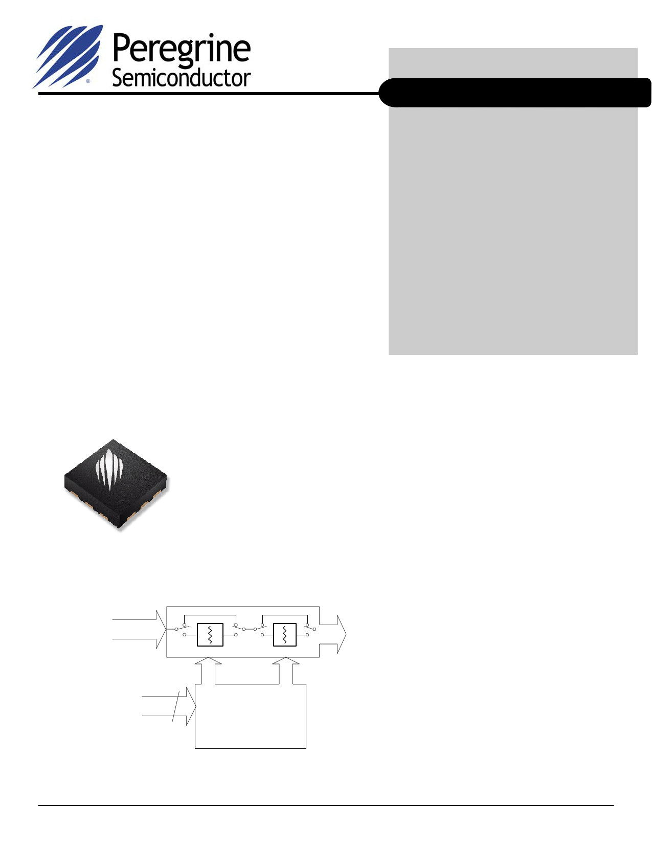
Figure 1. Package Type
12-lead 3x3x0.85 mm QFN Package
Figure 2. Functional Schematic Diagram
Switched Attenuator Array
RF Input
RF Output
Parallel Control 2
Control Logic
Interface
Document No. 70-0257-03 │ www.psemi.com
©2008-2009 Peregrine Semiconductor Corp. All rights reserved.
Page 1 of 8
1 page 
PE43204
Product Specification
Evaluation Kit
The 2-bit DSA EK Board was designed to ease
customer evaluation of Peregrine’s PE43204.
For automated programming, connect the test
harness provided with the EVK to the parallel port
of the PC and to the 6-pin header of the
PCB. Connect the loose wire of the supplied
cable to a power supply set at 3.3V DC. Set the
SP3T switches S1 and S2 to the ‘MIDDLE’ toggle
position. After downloading and installing the
DSA EVK software from www.psemi.com, run the
software and select ‘PE43204’ from the drop down
menu. Using the software, enable or disable
each setting to the desired attenuation state. The
software automatically programs the DSA each
time an attenuation state is enabled or disabled.
For manual programming, disconnect the test
harness provided with the EVK. Apply 3.3V to
the Vdd header pin and Ground to the GND
header pin. The DUT can be controlled two ways:
1. The mechanical switches in conjunction with
the VCTL pin can be used. Apply desired control
voltage to VCTL header pin. The top mechanical
switch controls the 6dB stage, the bottom
mechanical switch controls the 12dB stage. For
each switch, the left position is the 0V condition,
while the right position is the Vctrl condition. The
middle position leaves the control pin floating.
2. The CTL1 and CTL2 pins on the header can be
used. Each pin directly controls the 6dB and 12dB
stage respectively. The VCTL pin on the header is
left open. The mechanical switches may be left
uninstalled or must be kept in the middle position.
Note: To minimize switching time, C3 and C4 can
be removed.
Power-up Control Settings
The PE43204 will always power up into the state
determined by the voltages on the 2 control pins.
The DSA can be preset to any state within the 18
dB range by pre-setting the parallel control pins
prior to power-up. There is a 10µs delay between
the time the DSA is powered-up to the time the
desired state is set. If the control pins are left
floating during power-up, the device will default to
the minimum attenuation setting (insertion loss
state).
Document No. 70-0257-03 │ www.psemi.com
Figure 14. Evaluation Board Layouts
Peregrine Specification 101/0344
Figure 15. Evaluation Board Schematic
Peregrine Specification 102/0416
VCTL
VDD
CTL1
CTL2
J1
HEADER 3X2
11
33
55
22
44
66
S1
SS14MDP2
1
3
2
4
S2
SS14MDP2
1
3
2
4
C1
0.1µF
C2
100pF
C3
10PF
C4
10PF
J2
SMASM
1
Z=50 Ohm
1
NC
2
R F1
3
RF1
U1
PE43204
NC 9
RF2 8
RF2 7
13 CENTER GND PAD
J4
SMASM
1
De-embeding trace
Z=50 Ohm
J5
SMASM
1
Z=50 Ohm
J3
SMA SM
1
©2008-2009 Peregrine Semiconductor Corp. All rights reserved.
Page 5 of 8
5 Page | ||
| Páginas | Total 8 Páginas | |
| PDF Descargar | [ Datasheet PE43204.PDF ] | |
Hoja de datos destacado
| Número de pieza | Descripción | Fabricantes |
| PE43204 | (PE43x0x) 5-bit RF Digital Attenuator | Peregrine Semiconductor |
| PE43204 | RF Digital Attenuator | Peregrine Semiconductor |
| Número de pieza | Descripción | Fabricantes |
| SLA6805M | High Voltage 3 phase Motor Driver IC. |
Sanken |
| SDC1742 | 12- and 14-Bit Hybrid Synchro / Resolver-to-Digital Converters. |
Analog Devices |
|
DataSheet.es es una pagina web que funciona como un repositorio de manuales o hoja de datos de muchos de los productos más populares, |
| DataSheet.es | 2020 | Privacy Policy | Contacto | Buscar |